|
What follows is a synopsis of the changes to the basic KR2S design I will be including in my aircraft and the reasoning behind
these changes. The design changes are divided into Materials, Wings, Fuselage and Tail. Note that the opinions and decisions expressed
here around design changes to the KR2S from those listed on the KR plans are my own and in no way imply a recommendation of any kind.
If you are building your own KR please make sure you complete your own research if you intend to make changes to those stated on the
KR plans.
| Proposed Design Changes - Materials |
Structural Timber
| Plans State |
Sitka Spruce |
| Change To |
Yellow Cedar (also known as Alaskan Cedar) |
| Reasoning |
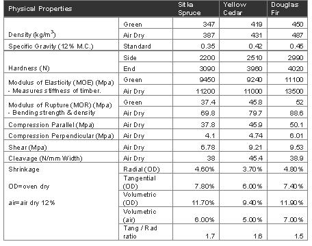
Alaskan Cedar is listed as a viable alternative to Sitka Spruce in the NASA document Aircraft Woods Report No.354.pdf.
Yellow Cedar is stronger and only slightly heavier than Spruce as per data sheet shown below
Yellow Cedar is easier to source in NZ and less expensive than Sitka Spruce. |
| Proposed Design Changes - Wings |
Airfoil
| Plans State |
RAF 48 design |
| Change To |
AS5048 at root tapering to AS5045 at tip. |
| Reasoning |
The primary reasons for using the new airfoil are that it reduces drag, increases lift and offers improved performance.
Also, given the AS5048 spar root is 8.19 high it is 17% stronger than the stock spar and adds almost 20% to the wing tank capacity.
The AS504x
page on the KRnet site details the history and development of the AS504x airfoil. |
Wing Incidence
| Plans State |
+3.5° at root
+0.5° at tip (giving -3.0° washout) |
| Change To |
+1.0° at root
-1.25° at tip (gives -2.25° washout) |
| Reasoning |
As per AS5048 installation instructions listed at the KRnet web page.
Also as per Mark Langford opinions on Wing Incidence found here. |
Inner Spars
| Plans State |
Solid forward and rear spar caps level to each tip. |
| Change To |
Laminated forward spar caps bent up at fuselage sides to form wing dihedral.
Laminated rear spar caps bent up and forward at fuselage sides. |
| Reasoning |
This change is suggested by Mark Langford on his opinions page found here.
Using laminated and bent spar caps will create a straight wing from the fuselage to the wing tip. The wing dihedral will be built into the
inner spars rather than using the Wing Attach Fittings. This will also enable simpler profiling of the wing airfoil when doing the GFRP
layups and also easier manufacturing of WAF's. |
Stub Wing Width
| Plans State |
83.00" wide at front spar.
84.00" wide at rear spar. |
| Change To |
87.00" wide at front spar.
88.00" wide at rear spar |
| Reasoning |
The increased Stub Wing width will compensate for the increase in cockpit width (see below). |
| Proposed Design Changes - Fuselage |
Firewall
| Plans State |
36.00" wide at top longeron
31.75" wide at bottom longeron
16.25" high between top and bottom longeron |
| Change To |
36.80" wide at top longeron
31.75" wide at bottom longeron
18.00" high between top and bottom longeron |
| Reasoning |
The primary reason to increase the depth of the firewall is to blend the bottom longeron of the fuselage with the new airfoil.
This change is suggested by Mark Langford on his miscellaneous page for builders starting new KR2S projects using the new AS504X airfoil
which can be found here.
The extra height means the firewall profile needs to be widened slightly at the top longeron to maintain the 82 degree side angle for the
front part of the fuselage.
The extra width/height will also create a slightly larger engine bay. |
Fuselage Boat Depth at Rear Spar
| Plans State |
20.00" at rear spar |
| Change To |
Reduce depth by 1.3" to allow for AS5048 airfoil. |
| Reasoning |
This change is suggested by Mark Langford on his miscellaneous page for builders starting new KR2S projects using the new AS504X airfoil
which can be found here.
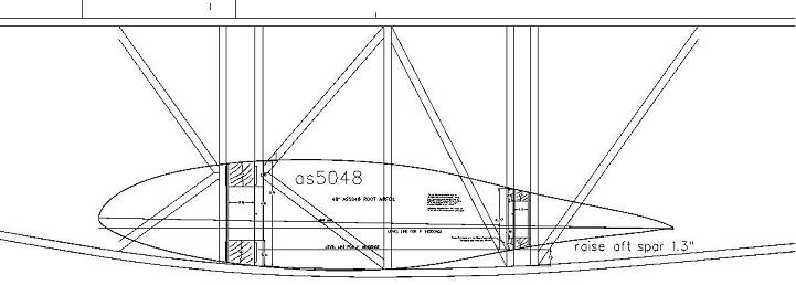
The existing bottom longeron of the fuselage was designed to blend with the RAF48 airfoil. Reducing the depth of the fuselage by 1.3" will
blend the fuselage to the new airfoil and also ensure the required wing incidence of +1 degree is built into the fuselage design.
The image below shows the new airfoil against the original fuselage and demonstrates why it makes sense to alter the boat depth. |

Fuselage Width at Rear Spar
| Plans State |
36.75" wide at top longeron at rear spar.
32.25" wide at bottom longeron at rear spar |
| Change To |
43.00" wide at top longeron at rear spar.
38.50" wide at bottom longeron at rear spar |
| Reasoning |
The KR is recognized as having a too narrow cockpit for two adults so most builders of KR's now widen the fuselage by 4-6 inches.
I am 510mm (20) wide across the shoulders and allowing for similar sized passenger, plus 1 clearance between pilot and passenger, plus 0.8
for the aicraft walls gives (20 + 20 + 1 + 0.8 + 0.8 = 42.6"). Rounded up this gives at total of 43".
This change is suggested by Mark Langford on his opinions page which can be found here. |
Widest Part of Fuselage
| Plans State |
38.00" wide at top longeron by front spar (by the pilots knees)
32.375" wide at bottom longeron by front spar |
| Change To |
43.00" wide at top longeron at pilots shoulders by the trailing edge of wing.
38.50" wide at bottom longeron at rear spar. |
| Reasoning |
Moving the widest part of fuselage to the rear spar by the trailing edge of the wing should improve the aerodynamics of the fuselage by
eliminating the area of higher drag over the airfoil where the fuselage narrows before the trailing edge of the wing and should result in a
smoother and more efficient airflow over the entire chord of the wing.
This change is suggested by Mark Langford on his opinions page which can be found here. |
| Proposed Design Changes - Tail |
Horizontal Stabiliser
| Plans State |
6' wide horizontal stabiliser.
Install with 0.00° of incidence. |
| Change To |
7' 6" wide horizontal stabiliser which includes 4 balance horns on each tip
Install with -0.75° incidence to give angular difference of 1.75° between the horizontal stabiliser and wing.
Use NACA63009 horizontal stabiliser profiles sourced from Mark Langfords web site. |
| Reasoning |
Other KR2S builders have reported that increasing the width of the horizontal stabiliser has significantly improved the pitch stability
of their aircraft which is reportedly pitch sensitive in the original design.
Using the NACA profile should also make the horizontal stabiliser more effective while also reducing drag.
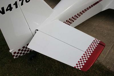
Aerodynamic balance horns should eliminate the requirement for an internal balance weight for the elevator which should reduce the overall
weight at the rear of the aircraft. The image below shows the balance horns fitted to Bill Clapps KR2S from the 2004 Gathering |
Vertical Stabiliser
| Plans State |
43" tailpost. |
| Change To |
45" tailpost
Include a 2" balance horn at top of rudder.
Use NACA63009 vertical stabiliser profiles sourced from Mark Langfords web site. |
| Reasoning |
The increased height of the tail should improve the effectiveness of the rudder.
Using the NACA profile should also make the vertical stabiliser more effective while also reducing drag. |
|