

kiwikr.co.nz
|
|
|
|
|
|
|||
Fuselage Frame | ||||||||
|
My fuselage will be constructed by building a top frame for the fuselage boat first then mounting templates over the top frame and
building the sides and bottom of the boat around the templates. This will ensure the longerons remain flat and not form a 'banana boat' and
also ensure the fuselage shape remains true and square. Other changes include: - Increasing the width of the fuselage to 43" at the pilots shoulders. - Reducing the depth of the fuselage boat at the rear wing spar by 1.3" to blend the fuselage to the AS5048 airfoil shape. - Increasing the height of the firewall between the upper and lower longerons by 1.75" to 18.0" and the width to 18.4". Conclusions after completing fuselage frame(31 July 2009) | ||||||||
 28 September 2008. Before starting the fuselage build I drew a centre line down my workbench to serve as a standard reference. Given the MDF
sheets used on the table top are already square and level, all I needed to use was a ruler and string line to do this. I checked the line with
a set square and a laser just to be sure however.
28 September 2008. Before starting the fuselage build I drew a centre line down my workbench to serve as a standard reference. Given the MDF
sheets used on the table top are already square and level, all I needed to use was a ruler and string line to do this. I checked the line with
a set square and a laser just to be sure however.
| ||||||||
 To draw the top longeron profile I marked out the vertical and horizontal cross member points down the table.
I used 18.40" for the width of the firewall at the top longeron (0.50" wider than plans state) to allow for the firewall depth of 18".
(18 * Tan 8 gives 2.53 which added to lower width of 15.885" gives 18.405" or 18.40" approx)
I then added 1.35" to the length of the top frame to allow for the tail post angle of 7 degrees. (10 * Tan 7 = 1.35). I marked this dimension,
measured back 5/8" for the tail post and 6mm for the bracing ply to give the rear most point for the upper longerons.
I then marked the widest point of the fuselage (21.5") and used a string line to set out the entire top longeron profile.
To draw the top longeron profile I marked out the vertical and horizontal cross member points down the table.
I used 18.40" for the width of the firewall at the top longeron (0.50" wider than plans state) to allow for the firewall depth of 18".
(18 * Tan 8 gives 2.53 which added to lower width of 15.885" gives 18.405" or 18.40" approx)
I then added 1.35" to the length of the top frame to allow for the tail post angle of 7 degrees. (10 * Tan 7 = 1.35). I marked this dimension,
measured back 5/8" for the tail post and 6mm for the bracing ply to give the rear most point for the upper longerons.
I then marked the widest point of the fuselage (21.5") and used a string line to set out the entire top longeron profile.
| ||||||||
 Next I drew in the inner line of the top longeron. This is 3/4" wide rather than 5/8" to allow for the angle of the vertical member ends and for
dressing the top longeron for the ply sides. I drew an actual size diagram of the angles and measured it manually but the formula (0.625 * Tan 8 =
0.088 + 0.625 = 0.71 or approx 3/4") gave the same result. (Note: I had worked this out previously as I had to make allowance for this width when ordering
my framing timber). I then drew in the top longeron doubler and cross members with diagonals and gussets. Of course this all sounds very straight forward
but the reality is it took five redraws of the longerons to get it sorted to my satisfaction :-). I am now awaiting the arrival of my framing timber so I
can start building.
Next I drew in the inner line of the top longeron. This is 3/4" wide rather than 5/8" to allow for the angle of the vertical member ends and for
dressing the top longeron for the ply sides. I drew an actual size diagram of the angles and measured it manually but the formula (0.625 * Tan 8 =
0.088 + 0.625 = 0.71 or approx 3/4") gave the same result. (Note: I had worked this out previously as I had to make allowance for this width when ordering
my framing timber). I then drew in the top longeron doubler and cross members with diagonals and gussets. Of course this all sounds very straight forward
but the reality is it took five redraws of the longerons to get it sorted to my satisfaction :-). I am now awaiting the arrival of my framing timber so I
can start building.
| ||||||||
 October 30th 2008. Very auspicious day today. My Yellow Cedar framing timber for the KR arrived from my timber supplier in Whangarei.
I didn't get a chance to open the packages as there was an SAA Auckland chapter meeting tonight I wanted to attend but at least it is here.
The wood arrived in two packages. One for the longerons and one for all the rest of the timber.
October 30th 2008. Very auspicious day today. My Yellow Cedar framing timber for the KR arrived from my timber supplier in Whangarei.
I didn't get a chance to open the packages as there was an SAA Auckland chapter meeting tonight I wanted to attend but at least it is here.
The wood arrived in two packages. One for the longerons and one for all the rest of the timber.
| ||||||||
 November 9th 2008. First day of actual construction today. After adding another layer of MDF to the benchtop to correct a couple of issues I
have had with the current benchtop sagging, I then made a start on the top longerons. I started by cutting and drilling 40mmx 40mm x 18mm
guide blocks for the top longerons. After drilling I had a lovely little pile of wooden blocks to play with. :-)
November 9th 2008. First day of actual construction today. After adding another layer of MDF to the benchtop to correct a couple of issues I
have had with the current benchtop sagging, I then made a start on the top longerons. I started by cutting and drilling 40mmx 40mm x 18mm
guide blocks for the top longerons. After drilling I had a lovely little pile of wooden blocks to play with. :-)
| ||||||||
 To mount the guide blocks for the port longeron I used the lines for the top longeron I have drawn on my workbench plus a
short length of pine I have dressed to the same dimensions as the top longeron (5/8" x 3/4") to align the blocks. I initially had these spaced
alternatively down the length of the table but changed this to support the inside of the curves only as the angles change further down the table.
To mount the guide blocks for the port longeron I used the lines for the top longeron I have drawn on my workbench plus a
short length of pine I have dressed to the same dimensions as the top longeron (5/8" x 3/4") to align the blocks. I initially had these spaced
alternatively down the length of the table but changed this to support the inside of the curves only as the angles change further down the table.
| ||||||||
 Next I had to thin down the timber for the top longerons as I had ordered the timber wider than I needed. I didn't know exactly what size I
required when I ordered it so erred on the safe side and ordered it as 7/8" x 5/8". I actually need 3/4" x 5/8" so used my thicknessor to
dress the timber.
Next I had to thin down the timber for the top longerons as I had ordered the timber wider than I needed. I didn't know exactly what size I
required when I ordered it so erred on the safe side and ordered it as 7/8" x 5/8". I actually need 3/4" x 5/8" so used my thicknessor to
dress the timber.
| ||||||||
 I then installed the top longeron between and around the guides. Having noted on other builders sites that the longerons are prone to cracking
when bending it around the curve where the fuselage tapers, I used towels soaked in hot water and wrapped around the longeron to soften the
wood before bending. I left the towels on for about 30 minutes then removed them and gently applied pressure to the longeron using clamps
leveraging against the mounting blocks to slowly and evenly draw the longeron around the curve.
I then installed the top longeron between and around the guides. Having noted on other builders sites that the longerons are prone to cracking
when bending it around the curve where the fuselage tapers, I used towels soaked in hot water and wrapped around the longeron to soften the
wood before bending. I left the towels on for about 30 minutes then removed them and gently applied pressure to the longeron using clamps
leveraging against the mounting blocks to slowly and evenly draw the longeron around the curve.
| ||||||||
 With the longeron fitted around all the guides here is the result. I have yet to trim the longeron to the desired length.
| ||||||||
 November 10th 2008. Mounted the guides for the starboard longeron on the table then pre-soaked and installed the longeron between and around
the guides. Also trimmed the longeron pieces so they hold against each other at the back end. They are not yet trimmed to their final length
where they meet the rudder tailpost.
November 10th 2008. Mounted the guides for the starboard longeron on the table then pre-soaked and installed the longeron between and around
the guides. Also trimmed the longeron pieces so they hold against each other at the back end. They are not yet trimmed to their final length
where they meet the rudder tailpost.
| ||||||||
|
November 13th 2008. Removed the inner forward guide blocks for the longerons to fit the inner longeron doublers. I then cut the 5/8 x 5/8 stock to
length and fitted the strips inside the outer longerons and used clamps to pull it all together. I then remounted the inner guide blocks to hold everything
in place.
| ||||||||
 November 15th 2008. Removed the inner guide blocks, doublers and longerons so I could cut and lay a piece of plastic under the wood so it
does not stick to the table when I start glueing. After thinking about how I was going to get the timber back in place with glue applied I decided to make
an adjustment to the inner guide blocks by sanding off one corner and using one screw to hold them in place. When I apply a clamp to the block it pivots
around the one screw and pulls the timber into place. Of the six guide blocks I have in place, if I fit the 1st, 2nd and 3rd and the 6th I can then
install the timber strip quite easily and then use clamps to pull it all together. Should make it considerably easier when glueing.
November 15th 2008. Removed the inner guide blocks, doublers and longerons so I could cut and lay a piece of plastic under the wood so it
does not stick to the table when I start glueing. After thinking about how I was going to get the timber back in place with glue applied I decided to make
an adjustment to the inner guide blocks by sanding off one corner and using one screw to hold them in place. When I apply a clamp to the block it pivots
around the one screw and pulls the timber into place. Of the six guide blocks I have in place, if I fit the 1st, 2nd and 3rd and the 6th I can then
install the timber strip quite easily and then use clamps to pull it all together. Should make it considerably easier when glueing.
| ||||||||
 November 16th 2008. Having not used West System Epoxy glue before, I decided I had better read the instruction manual and practice glueing up a couple
of offcuts to make sure I know how to mix things right. I will be using the West Systems recommended two pass approach for structural glueing. This
involves mixing epoxy and hardener initially without a filler and wetting the two faces to be glued with the mixture. Then add the filler (406) to the
remaining mixed epoxy to get it to mayonaise consistancy and apply this one of the wet faces then bring the surfaces together and clamp it all, removing
any epoxy squeezed out during clamping.
November 16th 2008. Having not used West System Epoxy glue before, I decided I had better read the instruction manual and practice glueing up a couple
of offcuts to make sure I know how to mix things right. I will be using the West Systems recommended two pass approach for structural glueing. This
involves mixing epoxy and hardener initially without a filler and wetting the two faces to be glued with the mixture. Then add the filler (406) to the
remaining mixed epoxy to get it to mayonaise consistancy and apply this one of the wet faces then bring the surfaces together and clamp it all, removing
any epoxy squeezed out during clamping.
| ||||||||
 I then set up for and proceeded to glue the port longeron and doubler. It went reasonably well. A couple of things I will do when I do the next one is
to mask off the sides of the timber to stop runs soaking into the timber and also lay down much more plastic to catch the drips. I am quite pleased with
the way it turned out. I managed to scrap off most off the excess glue that squeezed out of the joint but I will need to sand the joint to tidy it up a
bit once the glue has hardened off.
I then set up for and proceeded to glue the port longeron and doubler. It went reasonably well. A couple of things I will do when I do the next one is
to mask off the sides of the timber to stop runs soaking into the timber and also lay down much more plastic to catch the drips. I am quite pleased with
the way it turned out. I managed to scrap off most off the excess glue that squeezed out of the joint but I will need to sand the joint to tidy it up a
bit once the glue has hardened off.
| ||||||||
 With the port doubler out of the way I then proceeded to set up for and glue the starboard longeron and doubler. As the saying goes. You can never have
enough clamps.
With the port doubler out of the way I then proceeded to set up for and glue the starboard longeron and doubler. As the saying goes. You can never have
enough clamps.
| ||||||||
 Having completed all the glueing I could for the day I then moved on to cutting and fitting the cross members to the rear of the fuselage.
This has proved to be less difficult than I expected. I cut the 5/8 x 5/8 stock material roughly to length with a small hand coping saw then use my
sanding wheel to finish off each joint to a nice tight fit. If I take my time I can get the joints very clean and tidy. The smell of the yellow cedar
as it is being sanded is quite pleasant. Its been a busy old day. Hopefully I will be able to glue these cross members in tomorrow evening after work.
Having completed all the glueing I could for the day I then moved on to cutting and fitting the cross members to the rear of the fuselage.
This has proved to be less difficult than I expected. I cut the 5/8 x 5/8 stock material roughly to length with a small hand coping saw then use my
sanding wheel to finish off each joint to a nice tight fit. If I take my time I can get the joints very clean and tidy. The smell of the yellow cedar
as it is being sanded is quite pleasant. Its been a busy old day. Hopefully I will be able to glue these cross members in tomorrow evening after work.
| ||||||||
 November 17 2008. Removed the clamps from the glued longeron and doublers and checked the joint. Lifted the longerons to look at the underside.
There is a fair bit of epoxy run out from the joint and this will have to be sanded off. Before lifting the longeron I marked off the
firewall line on the longerons so I could use the sanding wheel to dress them off.
November 17 2008. Removed the clamps from the glued longeron and doublers and checked the joint. Lifted the longerons to look at the underside.
There is a fair bit of epoxy run out from the joint and this will have to be sanded off. Before lifting the longeron I marked off the
firewall line on the longerons so I could use the sanding wheel to dress them off.
| ||||||||
 I then used the sanding wheel to dress the longerons down to the firewall line. After completing this I then used a detail sander to remove
the squeezed out epoxy from the bottom of the longerons. Very slow process. Managed to only complete the port longeron.
I then used the sanding wheel to dress the longerons down to the firewall line. After completing this I then used a detail sander to remove
the squeezed out epoxy from the bottom of the longerons. Very slow process. Managed to only complete the port longeron.
| ||||||||
 November 18 2008. After thinking about it overnight I decided to run the longeron/doublers through the thicknessor to remove the excess epoxy. I did
this first thing in the morning before I went to work. I measured the longerons with a digital caliper before I started and found they measured 0.630" for
the vertical dimension so I had 0.005" to work with. After thicknessing, the longerons are now exactly 0.625" in the vertical dimension and virtually all
the epoxy runout has been removed. What little remained I was able to remove easily using a sanding block and fine 220 grit sandpaper.
November 18 2008. After thinking about it overnight I decided to run the longeron/doublers through the thicknessor to remove the excess epoxy. I did
this first thing in the morning before I went to work. I measured the longerons with a digital caliper before I started and found they measured 0.630" for
the vertical dimension so I had 0.005" to work with. After thicknessing, the longerons are now exactly 0.625" in the vertical dimension and virtually all
the epoxy runout has been removed. What little remained I was able to remove easily using a sanding block and fine 220 grit sandpaper.
| ||||||||
 After work I cut and fitted the cross members at the instrument panel position and at the shear web position behind the seat. Note from the photo that I
have also added a full length piece of 5/8" x 5/8" gusset between the front and rear cross braces for the shear web. This is to increase the surface area for the
shear web to stick to when fitted. There is a supplemental document that comes with the plans that recommends that this gusset be fitted and the shear web
thickness be increased from 2.5mm to 6mm to ensure the shear web is sufficiently strong enough so the pilot and passenger restraint straps do not rip out
during a crash impact. After cutting and fitting these I then checked I had enough sash clamps to do the gluing for the cross members. All looks good.
Should be able to glue these in place the day after tomorrow.
After work I cut and fitted the cross members at the instrument panel position and at the shear web position behind the seat. Note from the photo that I
have also added a full length piece of 5/8" x 5/8" gusset between the front and rear cross braces for the shear web. This is to increase the surface area for the
shear web to stick to when fitted. There is a supplemental document that comes with the plans that recommends that this gusset be fitted and the shear web
thickness be increased from 2.5mm to 6mm to ensure the shear web is sufficiently strong enough so the pilot and passenger restraint straps do not rip out
during a crash impact. After cutting and fitting these I then checked I had enough sash clamps to do the gluing for the cross members. All looks good.
Should be able to glue these in place the day after tomorrow.
| ||||||||
 Earlier in the evening I did a crush test on the sample blocks from gluing the port and starboard longerons and doublers. The standard requirement is
to create two sets of blocks to test. One is tested within a couple of days of gluing to ensure the batch of glue used is ok and the other is kept for
future use by CAA if required. I put the test block in my vice and attempted to break the epoxy glue joint in shear but this only resulted in the timber
failing and not the joint. It certainly gives me a lot of faith in this glue to hold the KR together.
Earlier in the evening I did a crush test on the sample blocks from gluing the port and starboard longerons and doublers. The standard requirement is
to create two sets of blocks to test. One is tested within a couple of days of gluing to ensure the batch of glue used is ok and the other is kept for
future use by CAA if required. I put the test block in my vice and attempted to break the epoxy glue joint in shear but this only resulted in the timber
failing and not the joint. It certainly gives me a lot of faith in this glue to hold the KR together.
| ||||||||
 November 20 2008. Set up for and glued the diagonal braces and the forward three cross members on the top fuselage frame. I used the two pass method as
recommended by West Systems where you wet the surfaces to be glued using just the epoxy and hardener mixture then add the filler to the mixture and
coat one surface of the two and bring them together. The picture was taken as I was removing the squeeezed out excess glue from the joints.
November 20 2008. Set up for and glued the diagonal braces and the forward three cross members on the top fuselage frame. I used the two pass method as
recommended by West Systems where you wet the surfaces to be glued using just the epoxy and hardener mixture then add the filler to the mixture and
coat one surface of the two and bring them together. The picture was taken as I was removing the squeeezed out excess glue from the joints.
| ||||||||
 This is the final setup I used for clamping the diagonal joints but it took a while to get to this configuration. I had worked out ahead of time how
I thought I would clamp everything but had not tried it. When I set up the clamps they caused the joints to slip and move. So the lesson learned is that
I need to do a practice run before glueing to make sure the clamping is going to work. The other thing I tried was using masking tape under the joints to
see if it will stop the excess glue under the joint from sticking to the timber.
This is the final setup I used for clamping the diagonal joints but it took a while to get to this configuration. I had worked out ahead of time how
I thought I would clamp everything but had not tried it. When I set up the clamps they caused the joints to slip and move. So the lesson learned is that
I need to do a practice run before glueing to make sure the clamping is going to work. The other thing I tried was using masking tape under the joints to
see if it will stop the excess glue under the joint from sticking to the timber.
| ||||||||
 November 21-22 2008. Removed the clamps from the gluing I did last night and sanded back the excess epoxy squeezed out of the joints. I then started
making the gussets for the joints.
November 21-22 2008. Removed the clamps from the gluing I did last night and sanded back the excess epoxy squeezed out of the joints. I then started
making the gussets for the joints.
| ||||||||
 November 23 2008. Made an early start out in the shed. Decided to build a box over the sanding wheel to try and stop the sanding dust from spreading
round the workshop. Although I am running a workshop vacuum, it is not picking up all the dust from the wheel and it is getting everywhere. The box has
done the trick. It has a hole in the top where I can look directly down on the piece of wood I am sanding but very little dust comes out of the hole as
the dust comes up vertically from the other upward side of the wheel and the hole is over the downward side. I will need to remove the box if I want to
use the belt.
November 23 2008. Made an early start out in the shed. Decided to build a box over the sanding wheel to try and stop the sanding dust from spreading
round the workshop. Although I am running a workshop vacuum, it is not picking up all the dust from the wheel and it is getting everywhere. The box has
done the trick. It has a hole in the top where I can look directly down on the piece of wood I am sanding but very little dust comes out of the hole as
the dust comes up vertically from the other upward side of the wheel and the hole is over the downward side. I will need to remove the box if I want to
use the belt.
| ||||||||
 I finished making all the gussets for the top frame. I decided to build small off centre cam-type blocks made from wood dowel to hold the gussets in
place as I went. I worked my way down the table cutting the gussets and blocks and setting up each joint as I went. This way I ensured I had the correct
number of blocks and enough clamps before I started gluing. A couple of the gussets were too narrow for a cam block so I used a trusty old clothes peg
to secure the gusset.
I finished making all the gussets for the top frame. I decided to build small off centre cam-type blocks made from wood dowel to hold the gussets in
place as I went. I worked my way down the table cutting the gussets and blocks and setting up each joint as I went. This way I ensured I had the correct
number of blocks and enough clamps before I started gluing. A couple of the gussets were too narrow for a cam block so I used a trusty old clothes peg
to secure the gusset.
| ||||||||
 I then set up and glued all the gussets and joints for all the remaining cross braces yet to be glued. A long days work but very satisfying.
| ||||||||
 November 24 2008. I removed the clamps and most of the small guide blocks holding the frame to the table. I then sanded the joints to remove the
excess epoxy. I used a detail sander with 100 grade paper to carefully remove the bulk of the residue then used a larger electric sander with 220 grade
paper to smooth off the surfaces. The result looks great. This photo was taken the next morning as I wasn't happy with the ones I took last night.
November 24 2008. I removed the clamps and most of the small guide blocks holding the frame to the table. I then sanded the joints to remove the
excess epoxy. I used a detail sander with 100 grade paper to carefully remove the bulk of the residue then used a larger electric sander with 220 grade
paper to smooth off the surfaces. The result looks great. This photo was taken the next morning as I wasn't happy with the ones I took last night.
| ||||||||
 November 30 2008. Today I measured and cut the centre line support for the side and bottom cross members.
| ||||||||
 December 01 2008. Trimmed and fitted the front centre line template support.
| ||||||||
 I then cut out and fitted the rear two cross templates. This is proving a lot more difficult than I anticipated as the angles on the sides and bottom
of the template have to be exactly right to ensure the 5/8 x 5/8 framing timber sits correctly. I cut and fitted the framing timber to the rear most
template to see what it would look like. In the photo you can see where the bottom longerons will fit in the corners between the upright and the cross
member. Also note that the angle for tailpost has already been cut in the centerline template although this is difficult to make out in the photo.
I then cut out and fitted the rear two cross templates. This is proving a lot more difficult than I anticipated as the angles on the sides and bottom
of the template have to be exactly right to ensure the 5/8 x 5/8 framing timber sits correctly. I cut and fitted the framing timber to the rear most
template to see what it would look like. In the photo you can see where the bottom longerons will fit in the corners between the upright and the cross
member. Also note that the angle for tailpost has already been cut in the centerline template although this is difficult to make out in the photo.
| ||||||||
 02 Dec - 03 Dec. Spent 2.5 hours yesterday and 6 hours today cutting out templates. This is proving to be a very slow process. I have now completed
seven out of the 14 templates but in the process I have stuffed up 2 others. I am at least learning how to use my bench saw to cut very accurate lines
and angles. Hopefully this knowledge will come in handy later on. Looking down the angles of the templates you can see the change in angle as you
approach the tail where the side is vertical.
02 Dec - 03 Dec. Spent 2.5 hours yesterday and 6 hours today cutting out templates. This is proving to be a very slow process. I have now completed
seven out of the 14 templates but in the process I have stuffed up 2 others. I am at least learning how to use my bench saw to cut very accurate lines
and angles. Hopefully this knowledge will come in handy later on. Looking down the angles of the templates you can see the change in angle as you
approach the tail where the side is vertical.
| ||||||||
 05 Dec - 10 Dec. Finally completed the fuselage templates after reworking quite a number of them after finding the dimensions of the earlier ones
I had cut on the bench saw were not accurate enough. Once all the templates had been cut and mounted I then measured, cut and mounted bracing blocks
between the templates to stiffen the whole frame and ensure the templates were exactly the correct distance from each other and 90 degrees to the
table top. The finished framework has taken considerably longer than I anticipated to complete but looks great and I am very pleased with it.
05 Dec - 10 Dec. Finally completed the fuselage templates after reworking quite a number of them after finding the dimensions of the earlier ones
I had cut on the bench saw were not accurate enough. Once all the templates had been cut and mounted I then measured, cut and mounted bracing blocks
between the templates to stiffen the whole frame and ensure the templates were exactly the correct distance from each other and 90 degrees to the
table top. The finished framework has taken considerably longer than I anticipated to complete but looks great and I am very pleased with it.
| ||||||||
 10-12 Dec Cut and mounted the vertical and diagonal frames at frame positions A, B & C. The nice part about building the airframe this
way is that once you cut one piece you can use it as a template to measure and cut the piece for the opposite side. I cut and fitted the
gussets and worked out clamping strategy then glued both Starboard and Port frames at A, B & C frame positions.
Although it is difficult to make out from the photo I am using popsicle sticks to hold the gussets in place. The popsicle sticks are held in place by
the clamps holding the vertical or diagonal side members and hold everything in place and apply plenty of pressure to ensure a good bond
by the West Systems epoxy. It is nearing mid summer here at the moment and the epoxy glue is going off quite quickly even using the slow hardener. I had
to make a seperate batch of glue for each side of the fuselage as the first batch had started to go off as I was just finishing the first side.
10-12 Dec Cut and mounted the vertical and diagonal frames at frame positions A, B & C. The nice part about building the airframe this
way is that once you cut one piece you can use it as a template to measure and cut the piece for the opposite side. I cut and fitted the
gussets and worked out clamping strategy then glued both Starboard and Port frames at A, B & C frame positions.
Although it is difficult to make out from the photo I am using popsicle sticks to hold the gussets in place. The popsicle sticks are held in place by
the clamps holding the vertical or diagonal side members and hold everything in place and apply plenty of pressure to ensure a good bond
by the West Systems epoxy. It is nearing mid summer here at the moment and the epoxy glue is going off quite quickly even using the slow hardener. I had
to make a seperate batch of glue for each side of the fuselage as the first batch had started to go off as I was just finishing the first side.
| ||||||||
 13 Dec. Removed clamps from yesterday's glueing then cut and fitted vertical and diagonal frames for position D on the starboard side of fuselage.
I initially stuffed this up as I measured the diagonal intersect position from the top of the fuselage (the side resting on the table) instead of the
bottom (the side furthest from the table). I re-measured the intersect position and then cut new diagonals. Note that the intersect position for
the diagonals has been increased to allow for the taller spars of the AS5048 airfoil.
13 Dec. Removed clamps from yesterday's glueing then cut and fitted vertical and diagonal frames for position D on the starboard side of fuselage.
I initially stuffed this up as I measured the diagonal intersect position from the top of the fuselage (the side resting on the table) instead of the
bottom (the side furthest from the table). I re-measured the intersect position and then cut new diagonals. Note that the intersect position for
the diagonals has been increased to allow for the taller spars of the AS5048 airfoil.15 Dec. Remade one of the diagonals for the C-D gap as I was not happy with the join to the vertical member. Also recut a couple of the gussets to get a closer tolerance fit to the angles. | ||||||||
 21 Dec. Cut and fitted the diagonals and vertical piece for the port C-D gap including the gussets.
22 Dec. Prepared and glued the port and starboard D verticals and the C-D gap diagonals and gussets. Also cut the verticals for the E,F,G,H,I and J positions. Finally I checked and adjusted the angles on the top of the C and D verticals to make sure they matched cleanly to the bottom longerons. | ||||||||
 27 Dec. Removed the front four templates and sanded the inside and outside of the joints glued to date to get rid of excess epoxy. Refitted the templates
which took most of the day getting them squared up again. In checking the templates I found that I had incorrectly measured the gap between the D and E
template by about 1/16". I removed the E template and shifted it rearward 1/16" to ensure the gap between the front of the D template and the front of the
E template was exactly 3".
27 Dec. Removed the front four templates and sanded the inside and outside of the joints glued to date to get rid of excess epoxy. Refitted the templates
which took most of the day getting them squared up again. In checking the templates I found that I had incorrectly measured the gap between the D and E
template by about 1/16". I removed the E template and shifted it rearward 1/16" to ensure the gap between the front of the D template and the front of the
E template was exactly 3".
| ||||||||
 29-30 Dec. Cut and fitted bottom cross members to positions B,C,D and E. Then set up clamp plates and clamps for cross members and bottom longerons.
30 Dec. Set up and glued the E vertical members, then glued the longerons to the A,B,C,D and E verticals. Finally fitted and glued the cross members to
the B,C,D and E positions. Clamped everything then went and had a cuppa. Came back to cut gussets for the bottom cross members when I noticed I couldn't
see gussets on the D cross member on the plans, nor could I see a D cross member. Quickly checked Mark Langfords and Darren Cromptons sites to confirm
the D cross member shouldn't be there then promptly removed said cross member and clamps before the glue set.
29-30 Dec. Cut and fitted bottom cross members to positions B,C,D and E. Then set up clamp plates and clamps for cross members and bottom longerons.
30 Dec. Set up and glued the E vertical members, then glued the longerons to the A,B,C,D and E verticals. Finally fitted and glued the cross members to
the B,C,D and E positions. Clamped everything then went and had a cuppa. Came back to cut gussets for the bottom cross members when I noticed I couldn't
see gussets on the D cross member on the plans, nor could I see a D cross member. Quickly checked Mark Langfords and Darren Cromptons sites to confirm
the D cross member shouldn't be there then promptly removed said cross member and clamps before the glue set.
| ||||||||
 01,02,04 Jan 2009. 2009 already. How time flies. Spent Jan 01 and 02 making gussets for joins between the bottom longerons and the vertical and bottom
cross members at positions A,B,C,D and E. Glued these gussets on the 4th. Popsicle sticks are the clamp-de-jeur.
01,02,04 Jan 2009. 2009 already. How time flies. Spent Jan 01 and 02 making gussets for joins between the bottom longerons and the vertical and bottom
cross members at positions A,B,C,D and E. Glued these gussets on the 4th. Popsicle sticks are the clamp-de-jeur.
| ||||||||
 Jan 05. Removed clamps from yesterdays glueing and set up clamps for vertical at F,G and H on both sides.
 | ||||||||
 07 Jan. Glued and clamped bottom longeron to F,G and H verticals.
| ||||||||
 Jan 08. Removed clamps from one side to inspect the joints.
 Jan 09. Came back next day and found the unclamped joints had come apart. Without the supporting gussets the green joint was obviously not strong enough to hold against the tension in the longeron. Won't make that mistake again. Will leave the joints as is till the weekend when I will clean it up and re-glue them. | ||||||||
 Jan 10. Removed templates A through F. The frame is actually beginning to look like a fuselage. I inspected all the joints and found that the bottom
cross members at position E was sitting about 1/16 of an inch high due to the bottom longeron being at an angle to the cross member. The same problem is
going to occur at position F so I trimmed 1/16 inch off the templates using a electric planner and carefully removed the existing cross member I had
fitted at position E and sanded the longeron back to clean wood. I then refitted the E & F templates and cut and fitted new cross members.
Jan 10. Removed templates A through F. The frame is actually beginning to look like a fuselage. I inspected all the joints and found that the bottom
cross members at position E was sitting about 1/16 of an inch high due to the bottom longeron being at an angle to the cross member. The same problem is
going to occur at position F so I trimmed 1/16 inch off the templates using a electric planner and carefully removed the existing cross member I had
fitted at position E and sanded the longeron back to clean wood. I then refitted the E & F templates and cut and fitted new cross members.
| ||||||||
 Jan 12. Cut gussets for the new cross members and then cleaned the joints which had failed at positions F,G and H and re-glued and clamped the bottom
longeron at these points. Then fitted the new bottom cross members at E and F and glued and fitted supporting gussets. I won't be removing the clamps from
positions G and H until the supporting gussets are also fitted.
Jan 12. Cut gussets for the new cross members and then cleaned the joints which had failed at positions F,G and H and re-glued and clamped the bottom
longeron at these points. Then fitted the new bottom cross members at E and F and glued and fitted supporting gussets. I won't be removing the clamps from
positions G and H until the supporting gussets are also fitted.
| ||||||||
 Jan 13. Removed templates at the E,F,G & H positions then trimmed 1/16" off the H template to ensure the H cross member doesn't sit too high
against the longerons. Then refitted the H template then set up wooden clamps to hold the G joint firmly while bending the timber up for the H
joint.
Jan 13. Removed templates at the E,F,G & H positions then trimmed 1/16" off the H template to ensure the H cross member doesn't sit too high
against the longerons. Then refitted the H template then set up wooden clamps to hold the G joint firmly while bending the timber up for the H
joint.
| ||||||||
 Jan 14-16. Cut and fitted cross member at I plus diagonals at E-F, F-G and cut and fitted the gussets for the starboard side.
Made the rest of the gussets for starboard side between G,H and I vertical and cross members.
Jan 14-16. Cut and fitted cross member at I plus diagonals at E-F, F-G and cut and fitted the gussets for the starboard side.
Made the rest of the gussets for starboard side between G,H and I vertical and cross members.Jan 17-18. Prepped the joints at H template for glueing by covering with plastic then glued the 'H' cross member and its gussets plus the starboard diagonals between E,F & G and their gussets. Once all this was clamped, cleaned and checked I then moved on and cut and fitted the diagonals and gussets for the ports side leaving them ready for glueing. Removed the clamps from yesterdays glueing. Checked the diagonals cut and fitted yesterday and removed and recut the F-G diagonal as I was not happy with the fit. Then set up and glued these diagonals and gussets. | ||||||||
 Jan 23. Have been out of action for the past week after a minor op laid me up so have not made much progress. Today I felt good enough to go out
and cut the bottom cross member at position J. Only in workshop for a short while though.
Jan 23. Have been out of action for the past week after a minor op laid me up so have not made much progress. Today I felt good enough to go out
and cut the bottom cross member at position J. Only in workshop for a short while though.Jan 28. Still haven't been up to working for a while plus took the family away for a bit of a break so have not achieved much. Today I spent an hour or so making the starboard diagonal between the H-I position plus a couple of the surrounding gussets. Feb 4. Cut the rest of the gussets for the diagonal member and bottom cross members at position I. These were then clamped and glued in the afternoon. Later in the evening I cut and fitted the diagonal member for the port H-I position. | ||||||||
 Feb 5th. Removed the clamps from yesterdays glueing and removed the template at position G then took this photo to show the progress to date.
I wouldn't say progress has been fast building the fuselage this way but I am happy with the way things are going. Note also in the photo that
sitting under the bench is a 6" x 2" length of rough sawn Yellow Cedar that I have purchased to make some more 5/8 x 5/8 lengths as I was running
out of the original order of this size of material. I should probably have ordered perhaps 20 or 30 feet extra of this size.
Feb 5th. Removed the clamps from yesterdays glueing and removed the template at position G then took this photo to show the progress to date.
I wouldn't say progress has been fast building the fuselage this way but I am happy with the way things are going. Note also in the photo that
sitting under the bench is a 6" x 2" length of rough sawn Yellow Cedar that I have purchased to make some more 5/8 x 5/8 lengths as I was running
out of the original order of this size of material. I should probably have ordered perhaps 20 or 30 feet extra of this size.
| ||||||||
 Feb 6th. Made new clamps for position I to hold the green joints in place while I bend the longerons up for position J.
| ||||||||
 I also remade the port diagonal between positions H-I as I was again not happy with the fit. Getting the diagonals to
be a close tolerance fit is quite difficult and requires patience and care when constructing the fuselage the way I have chosen to. Once the
port H-I diagonal was complete I cut and fitted the gussets for this member. Finally I cut and fitted the starboard diagonal between position I-J.
I also remade the port diagonal between positions H-I as I was again not happy with the fit. Getting the diagonals to
be a close tolerance fit is quite difficult and requires patience and care when constructing the fuselage the way I have chosen to. Once the
port H-I diagonal was complete I cut and fitted the gussets for this member. Finally I cut and fitted the starboard diagonal between position I-J.
| ||||||||
 Feb 9th. During the day I cut and fitted the port diagonal between the I-J positions then once this was done I cut and fitted all the gussets
for both the port and starboard diagonals, verticals and cross members at the I-J position. In the evening I glued all the parts between the I-J
positions as well as the port diagonal and gussets at the H-I position.
Feb 9th. During the day I cut and fitted the port diagonal between the I-J positions then once this was done I cut and fitted all the gussets
for both the port and starboard diagonals, verticals and cross members at the I-J position. In the evening I glued all the parts between the I-J
positions as well as the port diagonal and gussets at the H-I position.
| ||||||||
 Feb 10th. Removed the clamps from yesterdays glueing then removed the 'H' template.
Feb 10th. Cut and fitted both diagonal cross braces at the 'I' point plus made the gussets for these braces. | ||||||||
 Feb 12th. Cut and fitted the vertical and cross members at 'K' and 'L' points.
Feb 13th. Cut and fitted the vertical and cross members at 'M' point. | ||||||||
 Feb 14th. Added support blocks to the 'K', 'L' and 'M' templates to act as guides for the vertical and cross members.
Feb 15th. Cut and fitted a set of gussets each for the 'K', 'L' and 'M' cross members then set up and glued the vertical and cross members at the 'K', 'L' and 'M' points. | ||||||||
 Feb 15th. Then moved on and set up and glued the diagonal cross braces at the 'I' point.
| ||||||||
 Feb 16th. Removed the clamps from yesterdays glueing then removed the templates at 'J', 'K','L' and 'M'. I have left the 'N' template in place
as it is holding up the rear guide for the tail post. The 'N' template may end up being moved once I have put together the Horizontal Stabiliser.
After the templates were removed I found that the starboard vertical at 'K' was not in the correct place so I cut this out, sanded back the
longerons and made a new one. I then made a start on cutting and fitting the gussets that are yet to be fitted to the 'K','L' and 'M' points.
Feb 16th. Removed the clamps from yesterdays glueing then removed the templates at 'J', 'K','L' and 'M'. I have left the 'N' template in place
as it is holding up the rear guide for the tail post. The 'N' template may end up being moved once I have put together the Horizontal Stabiliser.
After the templates were removed I found that the starboard vertical at 'K' was not in the correct place so I cut this out, sanded back the
longerons and made a new one. I then made a start on cutting and fitting the gussets that are yet to be fitted to the 'K','L' and 'M' points.
| ||||||||
 I am very pleased with the way the fuselage has come up. It exactly matches what I originally drew and has no banana boat effect along the top
longeron.
I am very pleased with the way the fuselage has come up. It exactly matches what I originally drew and has no banana boat effect along the top
longeron.
| ||||||||
 Feb 17. Cut and fitted the starboard gussets for the 'K','L' and 'M' vertical members.
Feb 18. Cut and fitted the port gussets for the 'K','L' and 'M' vertical and cross members. Once these were complete I glued these in to place in the evening. Still very warm at night (25C) and very humid at the moment. | ||||||||
 I also cut and fitted the lower firewall engine mounting rail this afternoon. It is nice to finally work on something other than 5/8" x 5/8"
timber or a gusset. I started by measuring the depth of the rail against the firewall template and then cut the top section off the template using
my bench saw. I then used the cut off section as a pattern to draw onto the rail where I wanted to cut.
I also cut and fitted the lower firewall engine mounting rail this afternoon. It is nice to finally work on something other than 5/8" x 5/8"
timber or a gusset. I started by measuring the depth of the rail against the firewall template and then cut the top section off the template using
my bench saw. I then used the cut off section as a pattern to draw onto the rail where I wanted to cut.
| ||||||||
 Once the timber was cut using a jigsaw I then used the sanding wheel to finish and apply the correct angle to the edges where they meet the
fuselage side. It took a little fiddling to get it to match cleanly but I am happy with the result.
Once the timber was cut using a jigsaw I then used the sanding wheel to finish and apply the correct angle to the edges where they meet the
fuselage side. It took a little fiddling to get it to match cleanly but I am happy with the result.
| ||||||||
 I made up a pair of bracing blocks which match the contour of the fuselage so the sash clamp can clamp on to a flat
surface rather than the sloping sides of the fuselage.
I made up a pair of bracing blocks which match the contour of the fuselage so the sash clamp can clamp on to a flat
surface rather than the sloping sides of the fuselage.
| ||||||||
 Feb 19. I measured and cut the lower firewall shear brace this evening. With the lower engine mount clamped in position, I layed the 3.5"
x 5/8" timber across the bottom of the fueselage frame and drew the cutting lines onto the timber.
Feb 19. I measured and cut the lower firewall shear brace this evening. With the lower engine mount clamped in position, I layed the 3.5"
x 5/8" timber across the bottom of the fueselage frame and drew the cutting lines onto the timber.
| ||||||||
 Feb 20/21. After cutting I carefully used my sanding wheel to fit the shear brace tightly between the bottom longerons and the engine mount.
With this complete I then glued and clamped both the engine mount and the shear brace in place.
Feb 20/21. After cutting I carefully used my sanding wheel to fit the shear brace tightly between the bottom longerons and the engine mount.
With this complete I then glued and clamped both the engine mount and the shear brace in place.
| ||||||||
 Feb 22-28. I began the process of sanding the longerons to blend with the shear brace and the bottom cross braces. I initially tried using a
electric planer but found this a bit unwieldy so changed over to using a hand spoke planer, files and electric sander. I used my straight edge
to check the progress and although slow I am happy with the result.
Feb 22-28. I began the process of sanding the longerons to blend with the shear brace and the bottom cross braces. I initially tried using a
electric planer but found this a bit unwieldy so changed over to using a hand spoke planer, files and electric sander. I used my straight edge
to check the progress and although slow I am happy with the result.
| ||||||||
 For those that are interested the process I ended up using is as follows. I first drew a line on the side of the longeron
showing the depth I would plane down to. This was typically around 3mm for the front half of the longerons but tapered off to about 2mm by the rear.
For those that are interested the process I ended up using is as follows. I first drew a line on the side of the longeron
showing the depth I would plane down to. This was typically around 3mm for the front half of the longerons but tapered off to about 2mm by the rear.
| ||||||||
 I then used a spoke planer to remove the bulk of the wood from the longeron for each section I was working on.
| ||||||||
 I would check the the level at regular intervals to ensure I did not remove too much wood.
| ||||||||
 Once I had the timber down to close to what I needed, I then used a file to draw file the surfaces so they were square and smooth.
| ||||||||
 Finally I would lightly sand the surface with an electric sander using fine 220 grade paper.
| ||||||||
 Feb 28. I decided today that I wanted to see what the fuselage frame will look like up the right way so I removed the holding blocks and
flipped it over. Here is the photo. I have to say I think it looks pretty cool and I am pleased with the results so far.
Feb 28. I decided today that I wanted to see what the fuselage frame will look like up the right way so I removed the holding blocks and
flipped it over. Here is the photo. I have to say I think it looks pretty cool and I am pleased with the results so far.
| ||||||||
 Mar 01-03. Began the process of cleaning up all the glue joints of the boat. There is some excess glue on most of the joints and I have decided
to clean this off to expose the wood surfaces beneath. This will be important for ensuring the skin and any internal gussets that need
to be applied are mated against bare wood with no glue residue between the skin or gusset and the frame.
Mar 01-03. Began the process of cleaning up all the glue joints of the boat. There is some excess glue on most of the joints and I have decided
to clean this off to expose the wood surfaces beneath. This will be important for ensuring the skin and any internal gussets that need
to be applied are mated against bare wood with no glue residue between the skin or gusset and the frame.
| ||||||||
 Apr 26. Its been something like 8 weeks since I did any work on the KR. I spent the first 5-6 weeks out of the last 8 renovating the house
next to ours to get it ready for renting after we purchased it from our elderly neighbour. Also 3 weeks ago I managed to secure a new contract
after being out of work since December so I've spent considerable time getting up to speed on the new work environment. Today was the first
opportunity I have had to get back into it. Spent the day finishing off removing the excess glue from the boat joint surfaces. I found one
gusset during this process which had not been glued properly. One of the internal edges had a 0.5mm gap which had no glue in the joint. It is
difficult to see in the photo but I could slip a Stanley blade into the joint down to a depth of 3-4mm so I decided to cut the gusset out and
replace it.
Apr 26. Its been something like 8 weeks since I did any work on the KR. I spent the first 5-6 weeks out of the last 8 renovating the house
next to ours to get it ready for renting after we purchased it from our elderly neighbour. Also 3 weeks ago I managed to secure a new contract
after being out of work since December so I've spent considerable time getting up to speed on the new work environment. Today was the first
opportunity I have had to get back into it. Spent the day finishing off removing the excess glue from the boat joint surfaces. I found one
gusset during this process which had not been glued properly. One of the internal edges had a 0.5mm gap which had no glue in the joint. It is
difficult to see in the photo but I could slip a Stanley blade into the joint down to a depth of 3-4mm so I decided to cut the gusset out and
replace it.
| ||||||||
 I first used a hacksaw blade to cut out the bulk of the gusset.
| ||||||||
 I then used a sharp Stanley blade and a small file to remove the rest of the wood and any remaining glue from the joint. I am glad I removed the
gusset as I found the glue in the faulty joint was only bonding about 5-6mm of the 16mm of that face. This is how the joint looked after I had
finished cleaning it up.
I then used a sharp Stanley blade and a small file to remove the rest of the wood and any remaining glue from the joint. I am glad I removed the
gusset as I found the glue in the faulty joint was only bonding about 5-6mm of the 16mm of that face. This is how the joint looked after I had
finished cleaning it up.
| ||||||||
 Finally I cut a new gusset and fitted and glued this in place. The photo was taken as I was fitting the gusset and before it was glued in place.
| ||||||||
 Once I had completed the gusset and cleaning up the rest of the joints I moved on to reshaping the port top longeron to blend it with the
vertical members. Because of the way I built my fuselage I was left with an overhanging edge which needed to be planed down. You can see the
overhang in the photo at right. Note that this photo is of the starboard top longeron as I forgot to take a photo of the port longeron before
I started reshaping it.
Once I had completed the gusset and cleaning up the rest of the joints I moved on to reshaping the port top longeron to blend it with the
vertical members. Because of the way I built my fuselage I was left with an overhanging edge which needed to be planed down. You can see the
overhang in the photo at right. Note that this photo is of the starboard top longeron as I forgot to take a photo of the port longeron before
I started reshaping it.
| ||||||||
 I started by using my router to cut the face as close as I could to the desired shape. The router bit I used is one I purchased for the
job. It has a bearing at the base of the shaft close to the chuck which is used as the guide to prevent cutting too deep.
I started by using my router to cut the face as close as I could to the desired shape. The router bit I used is one I purchased for the
job. It has a bearing at the base of the shaft close to the chuck which is used as the guide to prevent cutting too deep.
| ||||||||
 Apr 27. Once I had finished with the router I then used a builders angle, electric detail sander, drawer file and sanding block to finish the
shaping and blending of the edge.
Apr 27. Once I had finished with the router I then used a builders angle, electric detail sander, drawer file and sanding block to finish the
shaping and blending of the edge.
| ||||||||
 This is the final result now ready for attaching the ply skin. I am quite pleased with the line of fuselage now that it trimmed.
| ||||||||
 Apr 28. Trimmed and shaped the starboard top longeron using the same technique as the port side. Went well except that I unfortunately stuffed
up during the sanding of the joint at the 'D' vertical side member and over sanded the vertical riser itself. This was caused by the member
being misaligned inwards from the top longeron by approx 1mm. As a result I had the detail sander at too great an angle and ended up creating
a dip in the face of the vertical member which is about 1.5mm shallower than the vertical line at its deepest point. The longeron has also been
slightly oversanded by about 0.5mm but I will be able to blend this out along the overall length of the longeron without it being too noticable.
Not very happy to have stuffed up like this but at least it won't be too hard to replace the damaged piece of wood. Also noticed when I took the
photo that I had oversanded the inside face as well so all the more reason to cut this piece out and replace it.
Apr 28. Trimmed and shaped the starboard top longeron using the same technique as the port side. Went well except that I unfortunately stuffed
up during the sanding of the joint at the 'D' vertical side member and over sanded the vertical riser itself. This was caused by the member
being misaligned inwards from the top longeron by approx 1mm. As a result I had the detail sander at too great an angle and ended up creating
a dip in the face of the vertical member which is about 1.5mm shallower than the vertical line at its deepest point. The longeron has also been
slightly oversanded by about 0.5mm but I will be able to blend this out along the overall length of the longeron without it being too noticable.
Not very happy to have stuffed up like this but at least it won't be too hard to replace the damaged piece of wood. Also noticed when I took the
photo that I had oversanded the inside face as well so all the more reason to cut this piece out and replace it.
| ||||||||
 Apr 29. Prepared to cut out the vertical side member by first flipping the frame over and fitting it back into the guide blocks on the table.
I then hunted out and and fitted the 'D' template again so I have a reference face to fit the new vertical member against.
Apr 29. Prepared to cut out the vertical side member by first flipping the frame over and fitting it back into the guide blocks on the table.
I then hunted out and and fitted the 'D' template again so I have a reference face to fit the new vertical member against.
| ||||||||
 Next I cut an accurate spacer to fit between the 'D' and 'E' vertical members. This took a while as I needed to get it exactly 2.375" wide. I
used my thicknessor and digital calipers to get it spot on. The fit between the members is firm at the center where the spar braces join to the
members but there is about a 0.25mm gap at the top and bottom between the 'D' member and the spacer. The member must have either had a slight bow
in it when I originally fit it or aquired one when I fit the diagonal spar braces on that side.
Next I cut an accurate spacer to fit between the 'D' and 'E' vertical members. This took a while as I needed to get it exactly 2.375" wide. I
used my thicknessor and digital calipers to get it spot on. The fit between the members is firm at the center where the spar braces join to the
members but there is about a 0.25mm gap at the top and bottom between the 'D' member and the spacer. The member must have either had a slight bow
in it when I originally fit it or aquired one when I fit the diagonal spar braces on that side.
| ||||||||
 May 09. Next I cut and sized some more 5/8 x 5/8 strips of yellow cedar. I thought I had a piece I could have used but when I inspected it
closely I found that the last 2" had been incorrectly thicknessed as it was at the run off end of the timber. Bit of a pain to have to cut out
two full lengths for a piece just 18" long but no doubt I will find uses for the rest.
May 09. Next I cut and sized some more 5/8 x 5/8 strips of yellow cedar. I thought I had a piece I could have used but when I inspected it
closely I found that the last 2" had been incorrectly thicknessed as it was at the run off end of the timber. Bit of a pain to have to cut out
two full lengths for a piece just 18" long but no doubt I will find uses for the rest.
| ||||||||
 May 09-10. After removing the original vertical member using a jigsaw, I then used a hacksaw blade and stanley blade to take the longerons back
to the original timber and finished the joints with a draw file and 220 grade sandpaper. I then cut and fitted the new vertical member to replace
the old one along with two new gussets. I then set up and glued the new pieces and clamped them in place. Note. I had taken a series of pictures
showing this whole process in far more detail but when I went to download them off the memory stick it appears they had not been saved. As such
I only have the finished photo to show.
May 09-10. After removing the original vertical member using a jigsaw, I then used a hacksaw blade and stanley blade to take the longerons back
to the original timber and finished the joints with a draw file and 220 grade sandpaper. I then cut and fitted the new vertical member to replace
the old one along with two new gussets. I then set up and glued the new pieces and clamped them in place. Note. I had taken a series of pictures
showing this whole process in far more detail but when I went to download them off the memory stick it appears they had not been saved. As such
I only have the finished photo to show.
| ||||||||
 May 10-13. Removed the clamps from the 'D' vertical member and cleaned up the joints. Then turned the boat over, fitted the front template and
laid up the top firewall brace against the front verticals to mark out for cutting the notches in the braces. Unfortunately I found that the
piece of Yellow Cedar I had for the top brace had warped so I will not be able to use it.
May 10-13. Removed the clamps from the 'D' vertical member and cleaned up the joints. Then turned the boat over, fitted the front template and
laid up the top firewall brace against the front verticals to mark out for cutting the notches in the braces. Unfortunately I found that the
piece of Yellow Cedar I had for the top brace had warped so I will not be able to use it.May 12. Order another piece of rough sawn 100mm x 50mm x 2m yellow cedar from local wood supplier. May 13. Yellow Cedar arrived today. | ||||||||
 May 17. This morning I visited with Mike Tunnicliffe another local aircraft builder who is building a Pietenpol which will use a steam powered
engined. Yes you read right, a steam powered engine. Mike has previously built a Jodel, a Corby Starlet to airframe completion and is currently
working on the Mosquito Project which is in the process of making its second full scale De Haviland Mosquito. This is a photo of Mike's workshop.
His explanation of how the steam engine will work was facinating. (It has been done before in the 1930's. Google the Bessler Steam Plane and you
should find it although Mike's engine will not be a total loss system like the Bessler.) It will be a pretty amazing plane, and very, very
quiet when he gets it finished.
May 17. This morning I visited with Mike Tunnicliffe another local aircraft builder who is building a Pietenpol which will use a steam powered
engined. Yes you read right, a steam powered engine. Mike has previously built a Jodel, a Corby Starlet to airframe completion and is currently
working on the Mosquito Project which is in the process of making its second full scale De Haviland Mosquito. This is a photo of Mike's workshop.
His explanation of how the steam engine will work was facinating. (It has been done before in the 1930's. Google the Bessler Steam Plane and you
should find it although Mike's engine will not be a total loss system like the Bessler.) It will be a pretty amazing plane, and very, very
quiet when he gets it finished.
| ||||||||
 After visiting Mike I came home and milled the rough sawn cedar down to the 3.5" x 5/8" required for the firewall brace.
| ||||||||
|
I then held it up to the airframe and penciled in the outline of the cutouts and drew in the cutting angle lines.
| ||||||||
 After drawing in the cutting angle lines this is the result.
| ||||||||
 May 18. I cut out the notches in the front cross brace this evening. Using my jigsaw I removed the bulk of the timber from the notch
taking care not to get to close to the final cutting lines.
May 18. I cut out the notches in the front cross brace this evening. Using my jigsaw I removed the bulk of the timber from the notch
taking care not to get to close to the final cutting lines.
| ||||||||
 Then used a wood rasp to take the wood down as close as I dared to the cutting lines. (Note: When I did the second notch I used a stanley blade
to shave the timber back to the cutting lines and I felt this worked much better than the rasp as I think you have more control over how much wood
is being pared away each time.)
Then used a wood rasp to take the wood down as close as I dared to the cutting lines. (Note: When I did the second notch I used a stanley blade
to shave the timber back to the cutting lines and I felt this worked much better than the rasp as I think you have more control over how much wood
is being pared away each time.)
| ||||||||
 Finally finished with a small metal file to draw file the finish. Then offered the finished piece up to airframe and removed any other small
amounts of timber necessary to fit it to the front of the airframe.
Finally finished with a small metal file to draw file the finish. Then offered the finished piece up to airframe and removed any other small
amounts of timber necessary to fit it to the front of the airframe.
| ||||||||
 This is the final fit on the port side.
| ||||||||
 And this is the final fit on the starboard side.
| ||||||||
 May 19. Tonight Mike Tunnicliffe came to visit to inspect my progress to date. Mike is certified to sign off on microlight wooden construction
so it was a relief when he had a look and was happy with my progress to date. After he left made a start on the rear top brace. I basically
repeated yesterdays exercise and marked up and cut out the notches. Here is a shot of me using a stanley blade to shave away the bulk of the timber
left after using the jigsaw.
May 19. Tonight Mike Tunnicliffe came to visit to inspect my progress to date. Mike is certified to sign off on microlight wooden construction
so it was a relief when he had a look and was happy with my progress to date. After he left made a start on the rear top brace. I basically
repeated yesterdays exercise and marked up and cut out the notches. Here is a shot of me using a stanley blade to shave away the bulk of the timber
left after using the jigsaw.
| ||||||||
 And this is the finished brace clamped behind the front brace. Have to say cutting the notches is particulary fiddly but taking your time
you can get a reasonable fit.
And this is the finished brace clamped behind the front brace. Have to say cutting the notches is particulary fiddly but taking your time
you can get a reasonable fit.
| ||||||||
 May 21. Tonight I started to cut and fit the filler blocks which sit on top of the top longeron behind the firewall braces. Could not work out why the
piece of timber I was working on was sitting proud of the forward cross braces until I woke up to the fact that I have cut the notches in the
firewall cross braces about 1/16" - 1/8" to high. Bugger! The photo shows the result. Will need to remake the firewall cross braces.
May 21. Tonight I started to cut and fit the filler blocks which sit on top of the top longeron behind the firewall braces. Could not work out why the
piece of timber I was working on was sitting proud of the forward cross braces until I woke up to the fact that I have cut the notches in the
firewall cross braces about 1/16" - 1/8" to high. Bugger! The photo shows the result. Will need to remake the firewall cross braces.
| ||||||||
 May 24. Milled a new piece of 3/8" x 3.5" timber today to remake the firewall cross braces. I marked up and cut out the rear cross brace first.
To be sure I had the correct width from the top of the timber I laid a piece of 5/8 x 5/8 along the brace and marked a pencil guide line.
May 24. Milled a new piece of 3/8" x 3.5" timber today to remake the firewall cross braces. I marked up and cut out the rear cross brace first.
To be sure I had the correct width from the top of the timber I laid a piece of 5/8 x 5/8 along the brace and marked a pencil guide line.
| ||||||||
 May 25. Tonight I marked up and cut out the forward cross brace again. Here is the photo of both the forward and rear cross braces mounted to
the fuselage frame. This time the notches are in the correct place! At least I will be able to reuse the pieces of timber from the previous efforts.
May 25. Tonight I marked up and cut out the forward cross brace again. Here is the photo of both the forward and rear cross braces mounted to
the fuselage frame. This time the notches are in the correct place! At least I will be able to reuse the pieces of timber from the previous efforts.
| ||||||||
 May 29. Not a happy tramper today. I decided to check the timber I cut on Tuesday by flipping the fuselage, fitting it back between the
guide blocks on the table and then fitting the firewall braces to the fuselage. Unfortunately I found that I have cut the braces about 5mm too
narrow and I am going to have to redo them again. It is getting very cold here at the moment so I packed it in for the night and decided to leave
this for the weekend.
May 29. Not a happy tramper today. I decided to check the timber I cut on Tuesday by flipping the fuselage, fitting it back between the
guide blocks on the table and then fitting the firewall braces to the fuselage. Unfortunately I found that I have cut the braces about 5mm too
narrow and I am going to have to redo them again. It is getting very cold here at the moment so I packed it in for the night and decided to leave
this for the weekend.
| ||||||||
 June 2nd-3rd. Ordered another piece of yellow cedar from my wood supplier today but decided to get dressed timber instead of rough sawn to
try and save a bit of time with thicknessing it. Reminded the supplier the wood was to be used in an aircraft build and had to be straight and
clean. The piece of timber that arrived is unfortunately not up to spec so will have to go out to the supplier and select a piece myself.
June 2nd-3rd. Ordered another piece of yellow cedar from my wood supplier today but decided to get dressed timber instead of rough sawn to
try and save a bit of time with thicknessing it. Reminded the supplier the wood was to be used in an aircraft build and had to be straight and
clean. The piece of timber that arrived is unfortunately not up to spec so will have to go out to the supplier and select a piece myself.
| ||||||||
 June 7th. Flew to Tauranga today on a DC3 with some friends to watch the D-Day commemorations being held at Tauranga airport. Beautiful
day at Tauranga and took many, many photos of the events and displays. I also managed to catch up with another KR builder here in New Zealand, Harry
Harris. Harry has had his KR2 completed and flying for quite some time but it was nice to catch up with someone who has been there and done that.
This is a photo of his plane. Note the unusual turtle deck design. Harry showed me how he had used 5mm Divinycell foam strips to make the turtle
deck using a strip planking technique. This has made for a very tidy and light weight turtle deck.
June 7th. Flew to Tauranga today on a DC3 with some friends to watch the D-Day commemorations being held at Tauranga airport. Beautiful
day at Tauranga and took many, many photos of the events and displays. I also managed to catch up with another KR builder here in New Zealand, Harry
Harris. Harry has had his KR2 completed and flying for quite some time but it was nice to catch up with someone who has been there and done that.
This is a photo of his plane. Note the unusual turtle deck design. Harry showed me how he had used 5mm Divinycell foam strips to make the turtle
deck using a strip planking technique. This has made for a very tidy and light weight turtle deck.
| ||||||||
 June 8th. Visited with my timber supplier out in west Auckland and bought three pieces of rough sawn timber today. Also visited my West Systems
glue supplier to buy some fast hardener as it is getting quite cold here with the temperatures at night around 4-5 degrees celcius. Not good for
glueing, even with fast hardener, so will just focus on cutting and fitting for the time being.
June 8th. Visited with my timber supplier out in west Auckland and bought three pieces of rough sawn timber today. Also visited my West Systems
glue supplier to buy some fast hardener as it is getting quite cold here with the temperatures at night around 4-5 degrees celcius. Not good for
glueing, even with fast hardener, so will just focus on cutting and fitting for the time being.
| ||||||||
 June 9th.Cut and thicknessed wood for a new set of firewall braces from one piece of the new timber.
June 10th. Checked the timber I cut on the 9th and found that the dressed surfaces had roughened up with a ripple effect across the face. It looks like the timber between the grain lines has contracted slightly to leave the ripple effect. I have decided to not use these pieces of timber as I am not sure what has caused this rippling and would rather not take the risk. | ||||||||
 June 14th. Fourth time lucky I hope. Cut and thicknessed another piece of wood from the new timber.
June 15th. Cut out the front firewall brace this evening. June 21st. Been bitterly cold this last week with temps down to zero degrees Celcius most nights. Have wimped out and not gone out to the shed for nearly a week. The days have been brilliantly fine however and today I finally got out to the shed for 3.5 hours and cut and fitted the rear firewall brace. I also cut and fitted the 5/8 x 5/8 cross member behind the firewall braces and the filler blocks between but I am not happy with the filler blocks as they are slightly thinner than the top piece of the firewall brace. | ||||||||
 June 23rd. Measured the thickness of the top of the firewall braces above the notches and found them to be 0.650". This is 0.025" more than the
standard 5/8" thickness. Thicknessed a piece of yellow cedar to 0.650" and made new filler blocks. The new blocks now blend evenly with the firewall
braces and I have sanded the blocks to blend with the cross member. I could have thicknessed the firewall braces but this seemed a simpler
solution at the time.
June 23rd. Measured the thickness of the top of the firewall braces above the notches and found them to be 0.650". This is 0.025" more than the
standard 5/8" thickness. Thicknessed a piece of yellow cedar to 0.650" and made new filler blocks. The new blocks now blend evenly with the firewall
braces and I have sanded the blocks to blend with the cross member. I could have thicknessed the firewall braces but this seemed a simpler
solution at the time.
| ||||||||
 June 28th. Slow day setting up for and glueing the front top firewall braces. This was quite fiddly and took me a while to get it
sorted but got there eventually. This is the first time I have used West Systems fast hardener as the temperatures have not got much above 12-14
degrees Celcius for the last month or two. I also made up a couple of wedges to use under the sash clamps so the clamp faces were square and not
angled.
June 28th. Slow day setting up for and glueing the front top firewall braces. This was quite fiddly and took me a while to get it
sorted but got there eventually. This is the first time I have used West Systems fast hardener as the temperatures have not got much above 12-14
degrees Celcius for the last month or two. I also made up a couple of wedges to use under the sash clamps so the clamp faces were square and not
angled.
| ||||||||
 June 29th. Removed the clamps from yesterdays glueing and tested the sample pieces to make sure the glue is ok. All looks good. Temperatures
overnight stayed pretty reasonable at about 10-12 degrees C. I have been told not to attempt any glueing if I expect the temperature to go below
10 degrees C. I also built a lifting frame this evening to lift the fuselage off the bench so I can access the table for joining ply together for
the fuselage sides and bottom. I temporarily held the lifting frame up with rope till I can put together something more permanent.
June 29th. Removed the clamps from yesterdays glueing and tested the sample pieces to make sure the glue is ok. All looks good. Temperatures
overnight stayed pretty reasonable at about 10-12 degrees C. I have been told not to attempt any glueing if I expect the temperature to go below
10 degrees C. I also built a lifting frame this evening to lift the fuselage off the bench so I can access the table for joining ply together for
the fuselage sides and bottom. I temporarily held the lifting frame up with rope till I can put together something more permanent.June 30th. Attached a couple of hooks to the frame tonight as a more permanent solution. I am fairly happy with the result. | ||||||||
 July 2nd. Marked out and cut a piece of 6mm ply for the top firewall shearbrace today.
July 5th. Set up for and glued the top firewall shear brace into place. I used just about every F clamp I own but it aint going anywhere and it is firmly clamped in place. I have also clamped a piece of 50x50 angle iron to the front of the cross brace as there is a slight bend in it. The angle iron acts as a straightedge against which I can clamp to hold it straight while the glue hardens. Once the glue has gone off the shearbrace will hold the cross brace straight. | ||||||||
 July 6th. Tested the samples from yesterdays glueing to make sure the glue had gone off properly before I removed the clamps from the shearweb.
I then flipped the fuselage over and used a router to dress the edges of the shear web.
July 6th. Tested the samples from yesterdays glueing to make sure the glue had gone off properly before I removed the clamps from the shearweb.
I then flipped the fuselage over and used a router to dress the edges of the shear web.
| ||||||||
 July 6th. This is the finished shearweb after dressing the edges with the router.
| ||||||||
 July 8th. Cut a strip of 2.5mm ply for the port and starboard gussets between the firewall shearweb and shelf. Once I had cut these to fit the
space I then cut and fit the 5/8 x 5/8 supports behind the strips. I will glue these into place later this week when the temperature improves a bit
as it has been getting down under 10 degrees Celcius again this week.
July 8th. Cut a strip of 2.5mm ply for the port and starboard gussets between the firewall shearweb and shelf. Once I had cut these to fit the
space I then cut and fit the 5/8 x 5/8 supports behind the strips. I will glue these into place later this week when the temperature improves a bit
as it has been getting down under 10 degrees Celcius again this week.
| ||||||||
 July 12th. Busy day today making a number of the components for the firewall. Started by making the lower gussets for the firewall. This is the
starboard one.
July 12th. Busy day today making a number of the components for the firewall. Started by making the lower gussets for the firewall. This is the
starboard one.
| ||||||||
 And this is the port one.
| ||||||||
 I then made the firewall shelf. Fitting this into place proved to be quite difficult but I finally figured it out. I started by fitting it
diagonally between the A and B vertical members.
I then made the firewall shelf. Fitting this into place proved to be quite difficult but I finally figured it out. I started by fitting it
diagonally between the A and B vertical members.
| ||||||||
 I then put a lever under the front edge in the middle of the firewall brace and gently levered the center of the brace up while pushing down
on the back edge of the shelf. This gradually allowed me to slide the shelf down into position.
I then put a lever under the front edge in the middle of the firewall brace and gently levered the center of the brace up while pushing down
on the back edge of the shelf. This gradually allowed me to slide the shelf down into position.
| ||||||||
 And to finally get it to fit into place.
| ||||||||
 After completing the shelf I then made the starboard gusset that sits under the shelf.
| ||||||||
 Then the port gusset.
| ||||||||
 Lastly I made up the pieces of 5/8 x 5/8 timber which sit under the edge of the shelf. Firstly the starboard one.
| ||||||||
 Then the port one. Hopefully the weather will warm up a bit this coming week and I will be able to glue some of these components into place.
| ||||||||
 July 19th. Finally had a day when it was warm enough to do some glueing. Because I am glueing the side gussets between the top firewall shearweb
and the firewall shelf today I need to take photos of the joints behind the gussets as these will not be visible once the skin is added to the
outside. This is the starboard shot.
July 19th. Finally had a day when it was warm enough to do some glueing. Because I am glueing the side gussets between the top firewall shearweb
and the firewall shelf today I need to take photos of the joints behind the gussets as these will not be visible once the skin is added to the
outside. This is the starboard shot.
| ||||||||
 And this is the port shot. Unfortunately it is not completely in focus but by the time I realised this I had already done the glueing so this is
the best shot I have.
And this is the port shot. Unfortunately it is not completely in focus but by the time I realised this I had already done the glueing so this is
the best shot I have.
| ||||||||
 This is the starboard side gusset after glueing.
| ||||||||
 This is the port side gusset after glueing.
| ||||||||
 I also glued the lower 2" firewall gussets today. This is the starboard one.
| ||||||||
 And this is the port lower corner 2" gusset.
| ||||||||
 July 20. 40th Anniversary of Neil Armstrong and Buzz Aldrin landing on the moon today. Removed clamps from yesterdays glueing and inspected
the glue joints on the side gussets. They look ok. I was going to glue in the firewall shelf this evening but the temperature dropped to below
10 degrees C so I called it a night and went inside. This is a photo of the port gusset.
July 20. 40th Anniversary of Neil Armstrong and Buzz Aldrin landing on the moon today. Removed clamps from yesterdays glueing and inspected
the glue joints on the side gussets. They look ok. I was going to glue in the firewall shelf this evening but the temperature dropped to below
10 degrees C so I called it a night and went inside. This is a photo of the port gusset.
| ||||||||
 And this is the starboard gusset.
| ||||||||
 July 21. Glued in the firewall shelf this evening as well as the two 5/8" x 5/8" side supports. It was certainly a lot easier to get the shelf
into place with the glue acting as a lubricant of sorts. I looked at glueing in the upper 2" corner firewall gussets as well tonight but the ones
I had previously cut were no longer a clean fit with the clamps holding down the shelf. I had not allowed for the shelf dropping slightly when the
clamps were fitted so I binned them both and will make up a couple of new ones on Thursday when I get out to the shed next.
July 21. Glued in the firewall shelf this evening as well as the two 5/8" x 5/8" side supports. It was certainly a lot easier to get the shelf
into place with the glue acting as a lubricant of sorts. I looked at glueing in the upper 2" corner firewall gussets as well tonight but the ones
I had previously cut were no longer a clean fit with the clamps holding down the shelf. I had not allowed for the shelf dropping slightly when the
clamps were fitted so I binned them both and will make up a couple of new ones on Thursday when I get out to the shed next.
| ||||||||
 July 24. I didn't get out to the shed on Thursday but I managed to get out tonight. I cut and fitted the two upper gussets under the shelf
and glued them into place. This is the port one.
July 24. I didn't get out to the shed on Thursday but I managed to get out tonight. I cut and fitted the two upper gussets under the shelf
and glued them into place. This is the port one.
| ||||||||
 And this is the starboard one.
| ||||||||
 31 July 2009. The fuselage frame is now basically complete. Next step is to fit the ply skin to the frame. Here is a photo of the frame as it
stands today Friday 31st July 2009.
31 July 2009. The fuselage frame is now basically complete. Next step is to fit the ply skin to the frame. Here is a photo of the frame as it
stands today Friday 31st July 2009.
| ||||||||
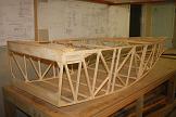
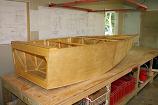

www.kiwikr.co.nz