

kiwikr.co.nz
|
|
|
|
|
|
|||
Fuselage Skin | ||||||||
|
My fuselage skin was attached to the fuselage frame after the frame has been completely built up. The skin is made of 2.5mm 5ply
Birch ply. The ply I purchased came in sheets 61" x 61" so I had to scarf join the ply at two points down the side and bottom of
the fuselage. | ||||||||
 26 July 2009. I took my sheets of ply down from the ceiling storage and picked out the sheet I will be using for the first side. The ply I have
is GL-II grade so it is not completely blemish free. I have picked the best sheets for the widest sections of the fuselage skin. I started by
measuring, marking and then cutting the first piece. I am using a jigsaw to cut the ply and a straight edge to keep the cut as straight as possible.
26 July 2009. I took my sheets of ply down from the ceiling storage and picked out the sheet I will be using for the first side. The ply I have
is GL-II grade so it is not completely blemish free. I have picked the best sheets for the widest sections of the fuselage skin. I started by
measuring, marking and then cutting the first piece. I am using a jigsaw to cut the ply and a straight edge to keep the cut as straight as possible.
| ||||||||
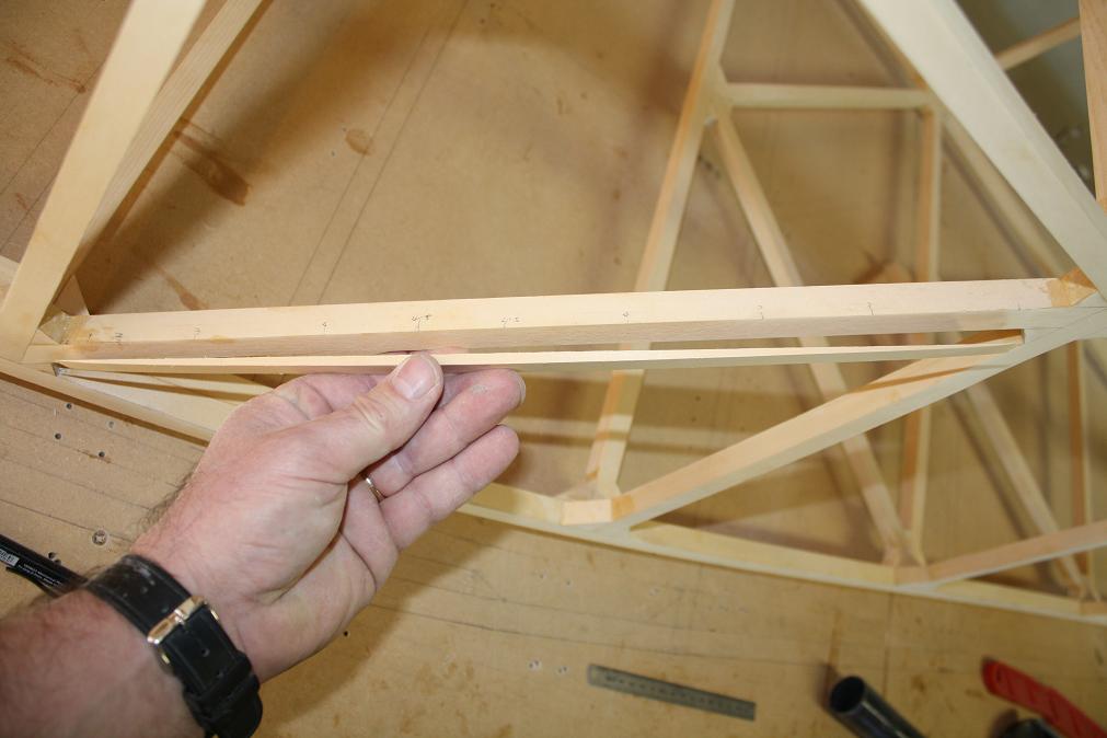
 I clamped the piece of ply to the side of the fuselage frame so I can work out where I need to trim the ply and where I need to scarf the
edges. As you can see the 61" sheet reaches to between the H and I vertical members. I will be marking it and cutting it to match the H member and
will scarf it over the H member.
I clamped the piece of ply to the side of the fuselage frame so I can work out where I need to trim the ply and where I need to scarf the
edges. As you can see the 61" sheet reaches to between the H and I vertical members. I will be marking it and cutting it to match the H member and
will scarf it over the H member.
| ||||||||
8 August 2009. The ply I have came in 5' sheets so it will need to be scarf joined along the side and bottom of the fuselage. I want to make
up a scarfing tool so I have had a look at other KR builders sites and at a few boat building sites on the web and the simplest tool I found
was at this site.
However before building my own version, I need to work out the angle to scarf the ply at. The KR builders manual is a bit vague and does not
give an exact figure for the scarf angle. It simply indicates the scarf join needs to be made over a vertical member and the diagram from the
manual indicates it should be as wide as the 5/8" timber. I had a look on the web at various sites and the consensus seemed to indicate that a
ratio of between 1:8 and 1:10 is normally used for ply scarf joints. Given 1:10 gives the most surface area to glue over I will use this.
I will center the scarf join over the vertical member when I attach it to the fuselage.
| ||||||||
 Not being much of a mathmatician I initially figured I would work out the scarf angle manually. Firstly I drew a line 100mm long and
then another 10mm line at right angles to the first. Then I drew in the long side (hypotenuse) of the triangle.
Not being much of a mathmatician I initially figured I would work out the scarf angle manually. Firstly I drew a line 100mm long and
then another 10mm line at right angles to the first. Then I drew in the long side (hypotenuse) of the triangle.
| ||||||||
 I then measured the angle using a protractor and read off 6 degrees as the angle. Now for a bit of math. Based on high school
Trigonometry we know that in a right angle triangle, the sine of one of the non 90 degree angles (theta) will equal the ratio of the length
of the opposite side divided by the length of the hypotenuse side. We know the angle of theta is 6 degrees and my calculator tells me the sine
of 6 degress equals 0.1045284. The length of the opposite side will be the thickness of the ply which is 2.5mm. So filling in the formula
we get 2.5/h = 0.1045284. And resolving for h we get h = 2.5/0.1045284 = 23.916931 or approximately 24mm. So what does this all mean. Well if
I draw a line 24mm from the edge of the ply, then a scarf angle of 6 degrees will meet the bottom edge of the ply and the 24mm line
simultaneously if it is set correctly.
I then measured the angle using a protractor and read off 6 degrees as the angle. Now for a bit of math. Based on high school
Trigonometry we know that in a right angle triangle, the sine of one of the non 90 degree angles (theta) will equal the ratio of the length
of the opposite side divided by the length of the hypotenuse side. We know the angle of theta is 6 degrees and my calculator tells me the sine
of 6 degress equals 0.1045284. The length of the opposite side will be the thickness of the ply which is 2.5mm. So filling in the formula
we get 2.5/h = 0.1045284. And resolving for h we get h = 2.5/0.1045284 = 23.916931 or approximately 24mm. So what does this all mean. Well if
I draw a line 24mm from the edge of the ply, then a scarf angle of 6 degrees will meet the bottom edge of the ply and the 24mm line
simultaneously if it is set correctly.
| ||||||||
|
(August 15. Bit of an update on the above. I decided to sit down and work out the angle properly after reading on Darren Cromptons site that
the angle should be 5.7 degrees. It bugged me that my math was so rusty that I couldn't work this out for myself so I reviewed a couple of
pages on the net to help refresh my memory about trigonometry and came up with the following calculations to enable me to derive the angle
for a 1:10 ratio. Interestingly this exercise did prove useful as it showed that my original calculation of 24mm was slightly short.) Step 1 - Find the length of the Hypotenuse of a triangle with sides 1mm by 10mm
Pythagorean Theory says  C^2 = A^2 + B^2
              therefore  C^2 = 1^2 * 10^2
                    ==>  C^2 = 101
                    ==>  C   = SQRT(101)
                    ==>  C   = 10.049876
This tells me that a triangle with sides 1mm by 10mm has a hypotenuse of length 10.05mm.Step 2 - Now find the angle (theta) between the Hypotenuse and the longest (adjacent) side.
Trigonometry says  sin(theta) = Opposite / Hypotenuse
        therefore  sin(theta) = 1 / 10.049876
              ==>  sin(theta) = 0.995037
              ==>  theta      = inverse(sin) of 0.995037
              ==>  theta      = 5.7105931 degrees
This tells me the angle between the hypotenuse and the longest adjacent side is 5.71 degrees.Step 3 - Find the Hypotenuse for a triangle with an opposite side of 2.5mm. (Depth of ply).
Trigonometry says  sin(theta) = Opposite / Hypotenuse
        therefore  sin(5.71)  = 2.5 / Hypotenuse
              ==>  Hypotenuse = 2.5 / sin(5.71)
              ==>  Hypotenuse = 2.5 / 0.0994934
              ==>  Hypotenuse = 25.12729mm
This tells me that for 2.5mm thick ply, a 1:10 cutting angle will have a cut face depth of 25mm. | ||||||||
 I went and purchased a Ryobi Trimmer (a sort of mini router) from a local hardware shop and a piece of 1.8mm steel plate used by builders
in houses. The trimmer cost about NZ$115 (roughly US$75). I bent the steel plate to the correct angle (it was already at about 4 degrees,
so all I had to do was bend it slightly more). Then measured, marked and drilled a pair of holes in the plate to allow it to be bolted to
the trimmer. I then cut a piece of 6mm ply to fit the plate and sanded this on the sanding wheel to an angle of 6 degress. Lastly I marked and
drilled a pair of holes in the ply to match the ones in the plate and bolted the jig to the trimmer. And this is the result.
I went and purchased a Ryobi Trimmer (a sort of mini router) from a local hardware shop and a piece of 1.8mm steel plate used by builders
in houses. The trimmer cost about NZ$115 (roughly US$75). I bent the steel plate to the correct angle (it was already at about 4 degrees,
so all I had to do was bend it slightly more). Then measured, marked and drilled a pair of holes in the plate to allow it to be bolted to
the trimmer. I then cut a piece of 6mm ply to fit the plate and sanded this on the sanding wheel to an angle of 6 degress. Lastly I marked and
drilled a pair of holes in the ply to match the ones in the plate and bolted the jig to the trimmer. And this is the result.
| ||||||||
 Here is another view.
| ||||||||
 I then made a test cut down the edge of a piece of ply and this is the result. I need to learn to go a little slower and do an initial
starting cut but the result is pretty tidy for a first effort. I will also look at investing in a laminate trimming bit so the cutter is not
chipping the ply as much as it cuts.
I then made a test cut down the edge of a piece of ply and this is the result. I need to learn to go a little slower and do an initial
starting cut but the result is pretty tidy for a first effort. I will also look at investing in a laminate trimming bit so the cutter is not
chipping the ply as much as it cuts.
| ||||||||
 13 August 2009. I marked out and cut the second piece of ply to match the original piece. I then marked out the scarf line and scarfed the
edge. Note that I have cut the scarfs such that the forward sheet will overlap the rear sheet when looking from the side. This will
ensure the forward joint does not face into the slipstream. The joint at the rear of fuselage will still be facing into the slipstream however
because the rear part of the fuselage skin won't get added till after I have finished off the installation of the horizontal and vertical
stabilisers.
13 August 2009. I marked out and cut the second piece of ply to match the original piece. I then marked out the scarf line and scarfed the
edge. Note that I have cut the scarfs such that the forward sheet will overlap the rear sheet when looking from the side. This will
ensure the forward joint does not face into the slipstream. The joint at the rear of fuselage will still be facing into the slipstream however
because the rear part of the fuselage skin won't get added till after I have finished off the installation of the horizontal and vertical
stabilisers.
| ||||||||
 15 August 2009. Today I marked out and cut the second set of side panels. I thought it better to do this now while the first set
aren't glued together and I could use them as a template. This is a shot of the scarfing jig I built in action. I have found that if I do a
couple of initial shallow cuts about 1/4 depth and then 2/3 depth before doing the full depth cut, the ply doesn't chip or split when doing
the final cut and gives a much smoother finish.
15 August 2009. Today I marked out and cut the second set of side panels. I thought it better to do this now while the first set
aren't glued together and I could use them as a template. This is a shot of the scarfing jig I built in action. I have found that if I do a
couple of initial shallow cuts about 1/4 depth and then 2/3 depth before doing the full depth cut, the ply doesn't chip or split when doing
the final cut and gives a much smoother finish.
| ||||||||
 After storing away the second set of panels I then set up for and glued the original set of panels. This is the setup I used.
Mike Tunicliffe told me that it is better to join scarf joints flat against your work bench rather than against the fuselage frame as you can
get the maximum leverage on the clamped joint. The piece of angle steel spreads the pressure evenly across the join.
After storing away the second set of panels I then set up for and glued the original set of panels. This is the setup I used.
Mike Tunicliffe told me that it is better to join scarf joints flat against your work bench rather than against the fuselage frame as you can
get the maximum leverage on the clamped joint. The piece of angle steel spreads the pressure evenly across the join.
| ||||||||
 August 16. This afternoon I removed the clamps and checked the join from yesterday. Unfortunately the join had slipped slightly when
I clamped it together and this resulted in a couple of high spots (0.5mm - 1mm) on the join which will face the outside
of the aircraft. I tried sanding these down but this only resulted in an unsightly and I think unacceptable finish.
I'm not happy with the result so I've decided to remove the join and redo it.
August 16. This afternoon I removed the clamps and checked the join from yesterday. Unfortunately the join had slipped slightly when
I clamped it together and this resulted in a couple of high spots (0.5mm - 1mm) on the join which will face the outside
of the aircraft. I tried sanding these down but this only resulted in an unsightly and I think unacceptable finish.
I'm not happy with the result so I've decided to remove the join and redo it.
| ||||||||
 I clamped the joined ply to the airframe to check and make sure I had sufficient material to remove the join and redo the scarf joint.
Fortunately there is enough material. It would have been a bit annoying to have to cut out another set of panels.
I clamped the joined ply to the airframe to check and make sure I had sufficient material to remove the join and redo the scarf joint.
Fortunately there is enough material. It would have been a bit annoying to have to cut out another set of panels.
| ||||||||
 So after removing the join and re-scarfing the edges, I re-glued and re-set the two pieces of ply for the second time. Hopefully this
time I have got it right.
So after removing the join and re-scarfing the edges, I re-glued and re-set the two pieces of ply for the second time. Hopefully this
time I have got it right.
| ||||||||
 August 17. After removing the ply from the clamps this evening I gave the joint a quick sand to smooth off the rough edge of glue and
this is the result. Much better than yesterdays effort.
August 17. After removing the ply from the clamps this evening I gave the joint a quick sand to smooth off the rough edge of glue and
this is the result. Much better than yesterdays effort.
| ||||||||
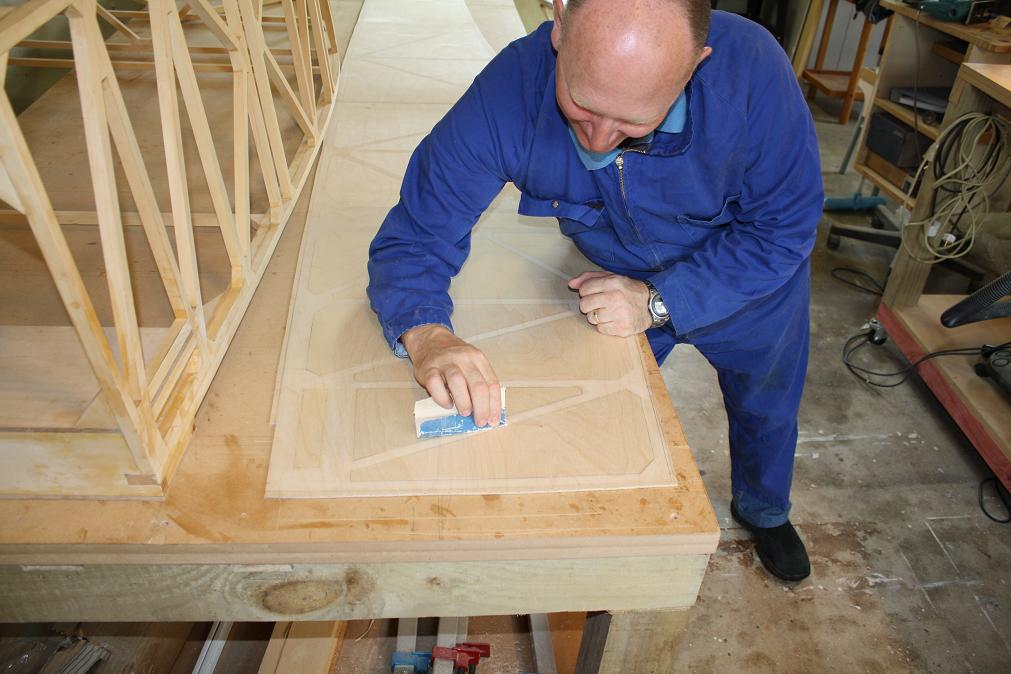
 After sanding the ply I attached it to the airframe so I could pencil in the vertical and diagonal frames as well as the longerons.
| ||||||||
 Although it is difficult to see the pencil lines are quite clear. These will be my glueing guidelines when I attach the ply to the
airframe. I also drew in a line approximately a 1/4" inch all the way around the edge so that I can roughly cut the panel to shape.
The panel will be flush finished using a router once it is glued to the airframe.
Although it is difficult to see the pencil lines are quite clear. These will be my glueing guidelines when I attach the ply to the
airframe. I also drew in a line approximately a 1/4" inch all the way around the edge so that I can roughly cut the panel to shape.
The panel will be flush finished using a router once it is glued to the airframe.
| ||||||||
 After trimming the panel this is the result.
| ||||||||
 I then trimmed and scarfed the end of the panel. I just used a stanley knife to trim the ply. It takes a few strokes to cut through
but the cut is very clean and gives a good edge to run the scarfing jig down. The scarf cut in the photo looks a bit crooked
but this is a bit of an optical illusion as the ply is bent up towards the camera.
I then trimmed and scarfed the end of the panel. I just used a stanley knife to trim the ply. It takes a few strokes to cut through
but the cut is very clean and gives a good edge to run the scarfing jig down. The scarf cut in the photo looks a bit crooked
but this is a bit of an optical illusion as the ply is bent up towards the camera.
| ||||||||
 I then scarfed a small piece of offcut to mate to the rear of the main panel while it is not attached to the airframe. The edge
of the scarf cut is very fragile and I want to protect it while it is being moved round the workshop.
I then scarfed a small piece of offcut to mate to the rear of the main panel while it is not attached to the airframe. The edge
of the scarf cut is very fragile and I want to protect it while it is being moved round the workshop.
| ||||||||
 The offcut is just lightly clamped in place for the time being.
| ||||||||
 With that all done I then set up and glued the second set of panels.
| ||||||||
 And then clamped them together the same as yesterday. These will be ready for me to sand and trim tomorrow.
| ||||||||
 August 18th. After removing the clamps and repeating yesterdays exercise I now have two side panels ready to be attached to the airframe.
| ||||||||
 August 23th. Only managed an hour or so on the KR over the weekend. I clamped the starboard skin to the airframe and drilled and screwed
6 small 4G x 16mm screws through the ply and into the frame to act as guides for when I glue the skin (hopefully) later this coming week.
August 23th. Only managed an hour or so on the KR over the weekend. I clamped the starboard skin to the airframe and drilled and screwed
6 small 4G x 16mm screws through the ply and into the frame to act as guides for when I glue the skin (hopefully) later this coming week.
| ||||||||
 September 5th. Its been a couple of weeks since I have been able to get out to the shed to work on the KR. I re-attached the skin today using
the guide screws to have a closer look at the fit. I had previously noted that the skin was not a flush fit against the diagonals between the
F-G and H-I verticals. All the other surfaces (longerons, verticals and diagonals) contact the skin evenly but these diagonals join two curving
points which results in the center of the diagonals being about 5mm inside the curved line formed by the skin. I had originally thought
I would just push the skin on to the diagonals when glueing it in place and secure it in place with staples.
September 5th. Its been a couple of weeks since I have been able to get out to the shed to work on the KR. I re-attached the skin today using
the guide screws to have a closer look at the fit. I had previously noted that the skin was not a flush fit against the diagonals between the
F-G and H-I verticals. All the other surfaces (longerons, verticals and diagonals) contact the skin evenly but these diagonals join two curving
points which results in the center of the diagonals being about 5mm inside the curved line formed by the skin. I had originally thought
I would just push the skin on to the diagonals when glueing it in place and secure it in place with staples.
| ||||||||
 However after mulling this over I have decided this is not such a good idea as the skin will have low spots over the two diagonals which
will probably need to filled at a later time if I want to get a smooth finish for painting. This will likely require quite a bit of resin
to fill and will add weight to the build. As such I have decided to remedy the situation by attaching a small fillet of timber to the outside
of each diagonal shaped to fill the gap between the existing frame and the skin.
However after mulling this over I have decided this is not such a good idea as the skin will have low spots over the two diagonals which
will probably need to filled at a later time if I want to get a smooth finish for painting. This will likely require quite a bit of resin
to fill and will add weight to the build. As such I have decided to remedy the situation by attaching a small fillet of timber to the outside
of each diagonal shaped to fill the gap between the existing frame and the skin.
| ||||||||
 I started by measuring the distance between the skin and the diagonals and drawing the major width points (1mm, 2mm, 3mm, 4mm etc) onto
the diagonals. I then removed the skin and cut and clamped a spare piece of 5/8" x 3" timber to the diagonal. (This timber is left over
from one of my failed attempts at making the top firewall braces.) I drew the measurements onto the timber, then filled in the curve I needed
to shape the fillet to.
I started by measuring the distance between the skin and the diagonals and drawing the major width points (1mm, 2mm, 3mm, 4mm etc) onto
the diagonals. I then removed the skin and cut and clamped a spare piece of 5/8" x 3" timber to the diagonal. (This timber is left over
from one of my failed attempts at making the top firewall braces.) I drew the measurements onto the timber, then filled in the curve I needed
to shape the fillet to.
| ||||||||
 Next I carefully sanded the edge of the timber to match the curved line I had drawn on it.
| ||||||||
 I then cut the fillet of timber from the larger piece using the bench saw.
| ||||||||
 A quick sand and the fillet is ready for glueing. I repeated the process for the second fillet then remounted the skin to the
fuselage and checked the fit. I had to do a little more fine sanding to get the curves fitting more snuggly and then I was ready to glue
them in place.
A quick sand and the fillet is ready for glueing. I repeated the process for the second fillet then remounted the skin to the
fuselage and checked the fit. I had to do a little more fine sanding to get the curves fitting more snuggly and then I was ready to glue
them in place.
| ||||||||
 Last step was to glue the fillets in place. I had drawn a couple of guide marks on the side of each fillet so I could line them up as
accurately as possible. Once the glue is dry tomorrow I will give them a gentle sand to remove any glue residue and to feather the ends
cleanly in to the diagonal faces.
Last step was to glue the fillets in place. I had drawn a couple of guide marks on the side of each fillet so I could line them up as
accurately as possible. Once the glue is dry tomorrow I will give them a gentle sand to remove any glue residue and to feather the ends
cleanly in to the diagonal faces.
| ||||||||
 September 6th. After removing the clamps and cleaning off the glue residue from the fillets this is the result. I re-attached the skin
to check the fit and it all looks good.
September 6th. After removing the clamps and cleaning off the glue residue from the fillets this is the result. I re-attached the skin
to check the fit and it all looks good.
| ||||||||
 I then repeated the exercise for the port side.
| ||||||||
 September 7th. After removing the clamps and cleaning up the glue residue the port side fillets look good. I will look to
glue the starboard skin to the frame in the next few days but this may need to wait till the weekend though as the temperature
overnight for the last few nights has been getting down below 10 degress Celcius and I would be happier if the temperature was
above 10 degrees before proceeding with glueing. I am also awaiting the delivery of some West Systems High Density Gap Filler
powder which I ordered today as I don't have sufficient powder remaining to make up the quantity of glue I will need to attach the skins.
September 7th. After removing the clamps and cleaning up the glue residue the port side fillets look good. I will look to
glue the starboard skin to the frame in the next few days but this may need to wait till the weekend though as the temperature
overnight for the last few nights has been getting down below 10 degress Celcius and I would be happier if the temperature was
above 10 degrees before proceeding with glueing. I am also awaiting the delivery of some West Systems High Density Gap Filler
powder which I ordered today as I don't have sufficient powder remaining to make up the quantity of glue I will need to attach the skins.
| ||||||||
 September 12th 2009. The target for today was to attach the starboard skin to the airframe. I asked a friend of mine, Murray Lee, who is into
aircraft as much as I am to give me a hand and after giving him a brief on what we would be doing we made a start. We firstly gave the ply
surfaces a light sanding to roughen the faces that would be glued. This is as per the NZ SAA Procedure Manual regarding glueing ply.
September 12th 2009. The target for today was to attach the starboard skin to the airframe. I asked a friend of mine, Murray Lee, who is into
aircraft as much as I am to give me a hand and after giving him a brief on what we would be doing we made a start. We firstly gave the ply
surfaces a light sanding to roughen the faces that would be glued. This is as per the NZ SAA Procedure Manual regarding glueing ply.
| ||||||||
 I then mixed up a fairly large batch of glue and Murray and I made a start applying it. However after about 15-20 minutes we struck a major
problem in that the glue started to go off rapidly in the bowls we were working from. The glue was exotherming so much
that it melted a hole in the bottom of one of the bowls. I should have realised this could occur as Mike Tunnicliffe had warned me that large
batches of epoxy need to be kept in wide shallow dishes otherwise it will cook off like this. The net result is that Murray
and I spent the next couple of hours wiping and scrapping the glue we had already applied from the fuselage and skin and getting the surfaces
back to the point where we had started from. Fortunately we had only got about half way through applying the glue so did not have too much
to remove. Still a major pain in the backside and not a mistake I will make again - ever.
I then mixed up a fairly large batch of glue and Murray and I made a start applying it. However after about 15-20 minutes we struck a major
problem in that the glue started to go off rapidly in the bowls we were working from. The glue was exotherming so much
that it melted a hole in the bottom of one of the bowls. I should have realised this could occur as Mike Tunnicliffe had warned me that large
batches of epoxy need to be kept in wide shallow dishes otherwise it will cook off like this. The net result is that Murray
and I spent the next couple of hours wiping and scrapping the glue we had already applied from the fuselage and skin and getting the surfaces
back to the point where we had started from. Fortunately we had only got about half way through applying the glue so did not have too much
to remove. Still a major pain in the backside and not a mistake I will make again - ever.
| ||||||||
 September 13th 2009. Second attempt at glueing the starboard skin to the fuselage. Murray came over about 9am and we made a start. After yesterdays
attempt we have learnt a few things. Firstly given the volume of glue we are making up, we will be using much wider bowls to hold the glue.
Secondly to speed up the application we will be using brushes instead of popsicle sticks to apply the glue. Popsicle sticks work fine for small
batches but not for large batches.
September 13th 2009. Second attempt at glueing the starboard skin to the fuselage. Murray came over about 9am and we made a start. After yesterdays
attempt we have learnt a few things. Firstly given the volume of glue we are making up, we will be using much wider bowls to hold the glue.
Secondly to speed up the application we will be using brushes instead of popsicle sticks to apply the glue. Popsicle sticks work fine for small
batches but not for large batches.
| ||||||||
 We got stuck in and after about 30 minutes we had the glue applied and the skin mounted on the airframe using the six guide screws I had
set up a week or so ago. We then began the process of stapling the skin to the frame through plastic tape. This took about 45 minutes to
complete.
We got stuck in and after about 30 minutes we had the glue applied and the skin mounted on the airframe using the six guide screws I had
set up a week or so ago. We then began the process of stapling the skin to the frame through plastic tape. This took about 45 minutes to
complete.
| ||||||||
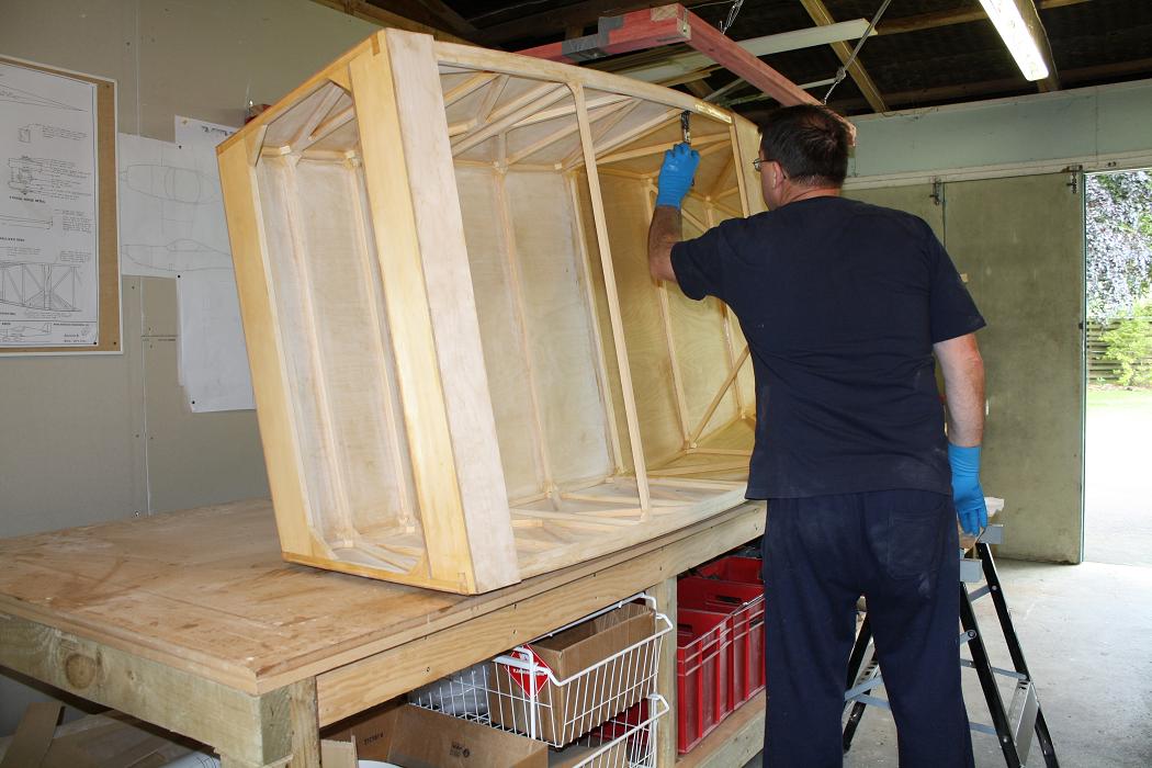
 We then stood the fuselage up on its side on a couple of work-mate portable benches and proceeded to clean up the glue residue and fillets. At
this point we found that a number of the joints were not sitting flush against the skin and we needed to apply clamps as well as staples to
bring the skin fully into contact with the frame. This finishing up took a further hour or so.
We then stood the fuselage up on its side on a couple of work-mate portable benches and proceeded to clean up the glue residue and fillets. At
this point we found that a number of the joints were not sitting flush against the skin and we needed to apply clamps as well as staples to
bring the skin fully into contact with the frame. This finishing up took a further hour or so.
| ||||||||
 After finally getting all the glue cleaned up and clamps applied something like 2.5 hours had gone past since starting. This was certainly
not one of the easiest tasks I have ever undertaken and I was very pleased to have Murray here to assist me as I could not have done it by myself.
After finally getting all the glue cleaned up and clamps applied something like 2.5 hours had gone past since starting. This was certainly
not one of the easiest tasks I have ever undertaken and I was very pleased to have Murray here to assist me as I could not have done it by myself.
| ||||||||
 The last thing I did was to move the airframe out of the garage and into the house. I did this because I used the slow hardener with the
epoxy so we had plenty of time to work while attaching the skin and as such I need to keep the temperature above 16 degress C while
the glue cures. At the moment the overnight average is around 9-10 C hence the move indoors. Fortunately I have a very tolerant wife
and family. As you can see the fuselage frame fits quite neatly in the family room of the house. With the heat pump going it is
easy to keep the temperature at the right level. I will let the epoxy cure for 48 hours to ensure it is well bonded.
The last thing I did was to move the airframe out of the garage and into the house. I did this because I used the slow hardener with the
epoxy so we had plenty of time to work while attaching the skin and as such I need to keep the temperature above 16 degress C while
the glue cures. At the moment the overnight average is around 9-10 C hence the move indoors. Fortunately I have a very tolerant wife
and family. As you can see the fuselage frame fits quite neatly in the family room of the house. With the heat pump going it is
easy to keep the temperature at the right level. I will let the epoxy cure for 48 hours to ensure it is well bonded.
| ||||||||
 September 15th. After waiting a couple of days to give the epoxy plenty of time to cure, I moved the airframe back out to the garage
and removed the staples from the fuselage using this pair of pincers that I bought for the purpose.
September 15th. After waiting a couple of days to give the epoxy plenty of time to cure, I moved the airframe back out to the garage
and removed the staples from the fuselage using this pair of pincers that I bought for the purpose.
| ||||||||
 This is the fuselage side with the staples and tape removed.
| ||||||||
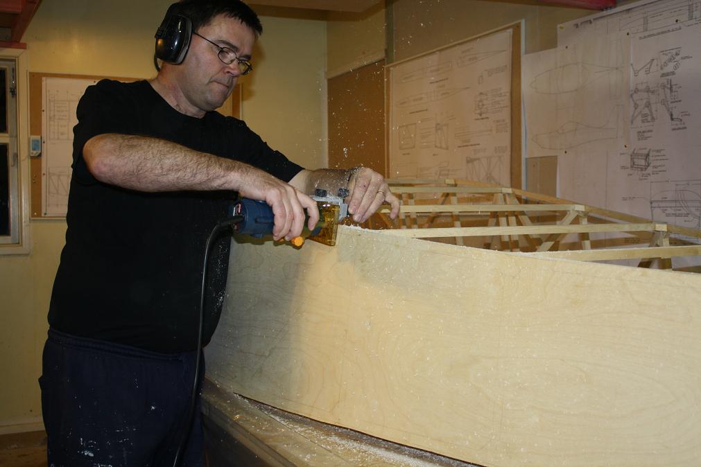 September 17th. Managed to get out to the garage again this evening to trim the starboard panel to match the frame. I used the trimmer
I purchased a month or so ago to do the scarf joints with. This is a lot easier to handle than a full size router and with a trimming
router bit fitted with a bearing on the end it was a relatively straight forward exercise to trim the excess ply.
September 17th. Managed to get out to the garage again this evening to trim the starboard panel to match the frame. I used the trimmer
I purchased a month or so ago to do the scarf joints with. This is a lot easier to handle than a full size router and with a trimming
router bit fitted with a bearing on the end it was a relatively straight forward exercise to trim the excess ply.
| ||||||||
 This is a close up of the trimmer set up I used.
| ||||||||
 This is the finished edge after routing and then using a file to tidy up any rough spots. Nice.
| ||||||||
 September 19th-20th. I had hoped to fit the port skin this weekend but time and an airshow at the local airport got in the way.
As such I just spent some time filling the staple holes in the skin with epoxy and then sanding back the skin to get a smooth finish.
Although the filled staple holes are a little unsightly because of the colour difference, the finished skin is very smooth and I am very
happy with the way it has come up.
September 19th-20th. I had hoped to fit the port skin this weekend but time and an airshow at the local airport got in the way.
As such I just spent some time filling the staple holes in the skin with epoxy and then sanding back the skin to get a smooth finish.
Although the filled staple holes are a little unsightly because of the colour difference, the finished skin is very smooth and I am very
happy with the way it has come up.
| ||||||||
 September 20th. And speaking of the airshow. There was a gorgeous Lancair 360 on the line which I spent ages looking over. This is one
beautiful aeroplane and has been finished immaculately. The photo does not do justice to the overall two tone metallic silver/bronze finish.
September 20th. And speaking of the airshow. There was a gorgeous Lancair 360 on the line which I spent ages looking over. This is one
beautiful aeroplane and has been finished immaculately. The photo does not do justice to the overall two tone metallic silver/bronze finish.
| ||||||||
 September 22th. Spent an hour this evening prepping the port skin for glueing to the frame. This involved giving the ply a light
sanding to roughen the surfaces that will be glued.
September 22th. Spent an hour this evening prepping the port skin for glueing to the frame. This involved giving the ply a light
sanding to roughen the surfaces that will be glued.
| ||||||||
 September 27th. This morning, with the help of Murray Lee, I attached the port skin to the fuselage frame. We followed the same process
as for the starboard skin and had the skin attached after about 1.5 - 2 hours of effort.
September 27th. This morning, with the help of Murray Lee, I attached the port skin to the fuselage frame. We followed the same process
as for the starboard skin and had the skin attached after about 1.5 - 2 hours of effort.
| ||||||||
 September 29th. I have waited 48hrs for the port skin glue to cure so it is as strong as possible. The average overnight temperature has
started to climb now that we are into the southern hemisphere spring so I didn't need to carry the airframe inside this time to keep it warm.
I removed the staples from the port skin tonight and then trimmed the skin flush with the frame using the mini trimmer/router. Afterwards I
cleaned up the edges with a file and sanded the staple holes in the skin. Tomorrow I will fill the holes ready for a further sanding on Thursday.
September 29th. I have waited 48hrs for the port skin glue to cure so it is as strong as possible. The average overnight temperature has
started to climb now that we are into the southern hemisphere spring so I didn't need to carry the airframe inside this time to keep it warm.
I removed the staples from the port skin tonight and then trimmed the skin flush with the frame using the mini trimmer/router. Afterwards I
cleaned up the edges with a file and sanded the staple holes in the skin. Tomorrow I will fill the holes ready for a further sanding on Thursday.
| ||||||||
 September 30th. Tonight I finshed off tidying up the edges of the skin and then filled the staple holes with epoxy glue and filler mix. I am back
to using fast hardener in the West Systems epoxy as there is not much to do and I want the glue to go off quickly. I apply the epoxy/filler mix
with a syringe (without a needle) I sourced from a local pharmacy. This allows me to place the glue more or less exactly where I want it to go.
Once the glue is applied I then use a stanley blade to work the mix into the holes and to remove any excess.
September 30th. Tonight I finshed off tidying up the edges of the skin and then filled the staple holes with epoxy glue and filler mix. I am back
to using fast hardener in the West Systems epoxy as there is not much to do and I want the glue to go off quickly. I apply the epoxy/filler mix
with a syringe (without a needle) I sourced from a local pharmacy. This allows me to place the glue more or less exactly where I want it to go.
Once the glue is applied I then use a stanley blade to work the mix into the holes and to remove any excess.
| ||||||||
 October 1st. Tonight I spent about half an hour tidying up the epoxy used to fill the staple holes then I moved on to marking out and cutting
the rear shear brace behind the seat. I will glue this into place either tomorrow or over the weekend.
October 1st. Tonight I spent about half an hour tidying up the epoxy used to fill the staple holes then I moved on to marking out and cutting
the rear shear brace behind the seat. I will glue this into place either tomorrow or over the weekend.
| ||||||||
 Sunday October 4th 2009. I've had a busy weekend with a group of other local aircraft builders coming over yesterday to have a look at my
progress and also to talk about the progress on their projects. It is great to catch up with other builders and hear about their progress
as I find it tends to get me inspired to go work on my project. I didn't get any building done yesterday after they left but today I got out to
shed all fired up. My aim for the day was to get the fuselage bottom skin marked out, cut and glued as well as finishing up the rear shear
brace by glueing it into place. I started by attaching the front sheet to the frame and running a pencil line under the sheet around the frame.
Sunday October 4th 2009. I've had a busy weekend with a group of other local aircraft builders coming over yesterday to have a look at my
progress and also to talk about the progress on their projects. It is great to catch up with other builders and hear about their progress
as I find it tends to get me inspired to go work on my project. I didn't get any building done yesterday after they left but today I got out to
shed all fired up. My aim for the day was to get the fuselage bottom skin marked out, cut and glued as well as finishing up the rear shear
brace by glueing it into place. I started by attaching the front sheet to the frame and running a pencil line under the sheet around the frame.
| ||||||||
 I then repeated this process for the rear sheet.
| ||||||||
 I then roughly cut out both pieces of ply approximately 10mm outside the lines I had drawn.
| ||||||||
 Then after re-assembling the scarfing jig and testing it, I scarfed both sheets ready for glueing.
| ||||||||
 Then glued and clamped the two sheets together.
| ||||||||
 With the bottom sheets out of the way I then finished trimming the rear shear brace before glueing it into place. Here is the obligatory photo
of yours truely applying the epoxy to the airframe.
With the bottom sheets out of the way I then finished trimming the rear shear brace before glueing it into place. Here is the obligatory photo
of yours truely applying the epoxy to the airframe.
| ||||||||
 This is the setup I used for clamping the shear brace into place. To clean up the glue under the brace I turned the airframe 90 degrees
off the table and supported the tail on a portable workbench while I sat on the floor and reached up between the bottom cross members to
remove the excess glue.
This is the setup I used for clamping the shear brace into place. To clean up the glue under the brace I turned the airframe 90 degrees
off the table and supported the tail on a portable workbench while I sat on the floor and reached up between the bottom cross members to
remove the excess glue.
| ||||||||
 October 5th 2009. After removing the clamps from the rear shear brace and cleaning up the edges this is the result. I am pleased with how it
has come out.
October 5th 2009. After removing the clamps from the rear shear brace and cleaning up the edges this is the result. I am pleased with how it
has come out.
| ||||||||
 October 6th 2009. After sanding the scarf joint to smooth out the glue residue and then trimming the ends off the panel this is what it
looks like mounted on the aircraft. I have already scarfed the rear edge so all that is needed is to mark and glue the panel.
I am trying to decide whether to staple the panel or use weights to secure it while the glue sets. I will need to have a think about this.
October 6th 2009. After sanding the scarf joint to smooth out the glue residue and then trimming the ends off the panel this is what it
looks like mounted on the aircraft. I have already scarfed the rear edge so all that is needed is to mark and glue the panel.
I am trying to decide whether to staple the panel or use weights to secure it while the glue sets. I will need to have a think about this.
| ||||||||
 October 10th 2009. Drove out to Pukekohe this afternoon (about 15 - 20 km south of where I live) to visit with Paul Blackmore who is building
a Sonex. I had an enjoyable afternoon talking aircraft, building techniques and tools with Paul. Gotta say I really like the Sonex. Its plans
are very comprehensive and its build process seems very straight forward. If I were to build a metal aircraft it would probably be a Sonex.
October 10th 2009. Drove out to Pukekohe this afternoon (about 15 - 20 km south of where I live) to visit with Paul Blackmore who is building
a Sonex. I had an enjoyable afternoon talking aircraft, building techniques and tools with Paul. Gotta say I really like the Sonex. Its plans
are very comprehensive and its build process seems very straight forward. If I were to build a metal aircraft it would probably be a Sonex.
| ||||||||
 October 10th 2009. I flipped the airframe over tonight and attached the bottom panel to the airframe with clamps so I could pencil in the
outlines of the longerons and cross members to use these as guides for glueing.
October 10th 2009. I flipped the airframe over tonight and attached the bottom panel to the airframe with clamps so I could pencil in the
outlines of the longerons and cross members to use these as guides for glueing.
| ||||||||
 I had previously noted that the bottom cross member at the 'G' position was bent slightly which I believe has been caused by the compressive
loads being applied to it by the curve in the cross members at this point. Mike Tunnicliffe recommended that I straighten this bend before
attaching the bottom panel. After thinking through a number of ways to do this I decided on the method described below.
I had previously noted that the bottom cross member at the 'G' position was bent slightly which I believe has been caused by the compressive
loads being applied to it by the curve in the cross members at this point. Mike Tunnicliffe recommended that I straighten this bend before
attaching the bottom panel. After thinking through a number of ways to do this I decided on the method described below.
| ||||||||
 I have used a straight piece of 2"x 3" framing timber cut to length as a backframe and laid a piece of 5/8" x 5/8" timber down the centre so I
could attach six small pieces of 5/8" x 5/8" either side of it to act as guides. I have then added a couple of pieces of 2.5mm ply to the face
of the 2"x 3" between to guide blocks to elevate the jig off the cross member. I then attached this jig to the cross member and this is the
result. Not perfect but a whole heap straighter than it was and it sits high enough that I will be able to clean up any glue squeezed out during
clamping. I will put a layer of plastic between the jig and the cross member before applying the glue and the bottom skin.
I have used a straight piece of 2"x 3" framing timber cut to length as a backframe and laid a piece of 5/8" x 5/8" timber down the centre so I
could attach six small pieces of 5/8" x 5/8" either side of it to act as guides. I have then added a couple of pieces of 2.5mm ply to the face
of the 2"x 3" between to guide blocks to elevate the jig off the cross member. I then attached this jig to the cross member and this is the
result. Not perfect but a whole heap straighter than it was and it sits high enough that I will be able to clean up any glue squeezed out during
clamping. I will put a layer of plastic between the jig and the cross member before applying the glue and the bottom skin.
| ||||||||
 Monday October 12th 2009. Started out this evening by sanding the glue lines on the bottom skin of the fuselage ready for glueing. I need an extra
pair of hands to do the glueing so will wait till this coming weekend before doing this.
Monday October 12th 2009. Started out this evening by sanding the glue lines on the bottom skin of the fuselage ready for glueing. I need an extra
pair of hands to do the glueing so will wait till this coming weekend before doing this.
| ||||||||
 Sunday November 8th 2009. After cogitating over the attachment of the bottom skin for nearly a month I finally pulled finger and managed
to get the skin attached today. I started by fitting the airframe back into its support blocks to ensure it is secure and square while the
glue cures. I then built a set of support frames down the center of the airframe using 65mm x 18mm dressed pine to support the center of
each fuselage cross member. These supports will transfer the load of the weights used to secure the skin and will also ensure the cross
members don't flex when stapling the joints. The frame at the G position will now straighten the G cross member instead of the piece
of framing timber I was going to use. A finger of 5/8" x 5/8" block screwed to the frame was all that was required and it should make
it easier to access the cross member to clean up any excess glue as well.
Sunday November 8th 2009. After cogitating over the attachment of the bottom skin for nearly a month I finally pulled finger and managed
to get the skin attached today. I started by fitting the airframe back into its support blocks to ensure it is secure and square while the
glue cures. I then built a set of support frames down the center of the airframe using 65mm x 18mm dressed pine to support the center of
each fuselage cross member. These supports will transfer the load of the weights used to secure the skin and will also ensure the cross
members don't flex when stapling the joints. The frame at the G position will now straighten the G cross member instead of the piece
of framing timber I was going to use. A finger of 5/8" x 5/8" block screwed to the frame was all that was required and it should make
it easier to access the cross member to clean up any excess glue as well.
| ||||||||
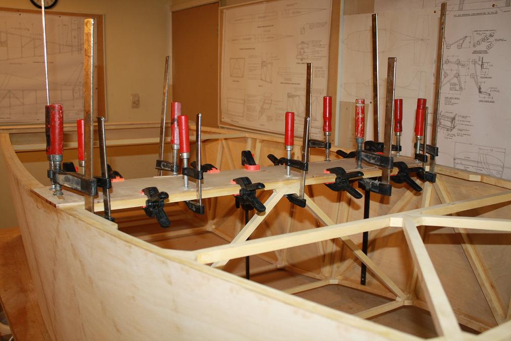
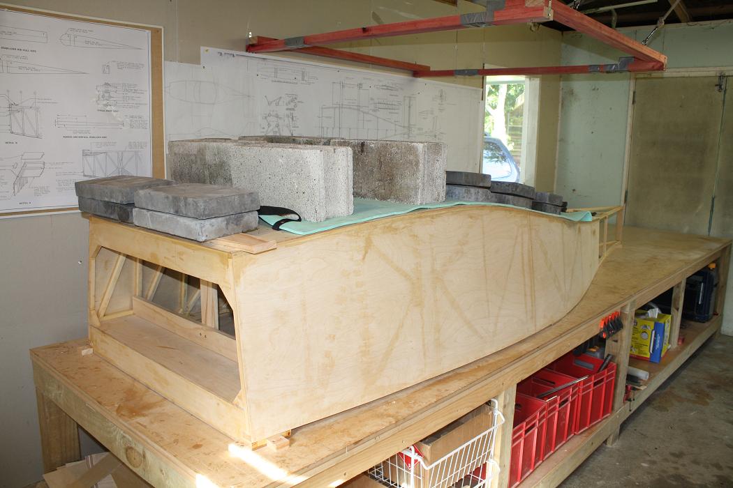 After building up the internal frame in the morning, my son Jeremy helped me glue and attach the skin to the airframe in the afternoon.
The process took quite a bit of time and effort and I was very glad to have Jeremy's assistance. We followed the same process as with the
previous skins by firstly applying epoxy to both the skin and the frames to wet both surfaces, then after mixing in the filler powder to the
epoxy, we applied the filler epoxy to the frame only. We then quickly attached the skin to the frame using small alignment screws and this
was followed by applying staples to secure the skin along all edges and cross members. Then we flipped the fuselage over and I cleaned up the
excess glue squeezed out of the joints. The final step was to turn the airframe back over and fit it into the support blocks once again and
apply weights over a couple of camping mats which are there to protect the ply surface.
After building up the internal frame in the morning, my son Jeremy helped me glue and attach the skin to the airframe in the afternoon.
The process took quite a bit of time and effort and I was very glad to have Jeremy's assistance. We followed the same process as with the
previous skins by firstly applying epoxy to both the skin and the frames to wet both surfaces, then after mixing in the filler powder to the
epoxy, we applied the filler epoxy to the frame only. We then quickly attached the skin to the frame using small alignment screws and this
was followed by applying staples to secure the skin along all edges and cross members. Then we flipped the fuselage over and I cleaned up the
excess glue squeezed out of the joints. The final step was to turn the airframe back over and fit it into the support blocks once again and
apply weights over a couple of camping mats which are there to protect the ply surface.
| ||||||||
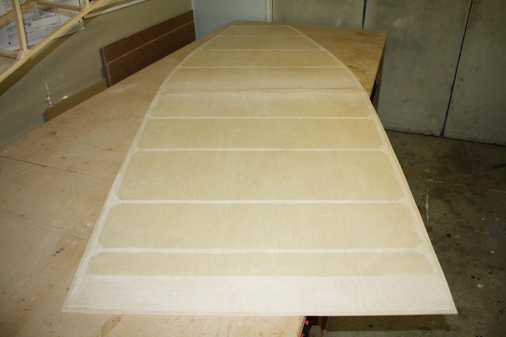
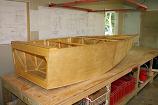
 Monday November 9th 2009. This evening I removed the weights and staples from the top of the skin, then flipped the airframe over to remove
the internal support frame. Have to say the boat looks great. I flipped the frame back over and trimmed the edges using the trimmer then
started working my way round the skin tidying up the edges with a file.
Monday November 9th 2009. This evening I removed the weights and staples from the top of the skin, then flipped the airframe over to remove
the internal support frame. Have to say the boat looks great. I flipped the frame back over and trimmed the edges using the trimmer then
started working my way round the skin tidying up the edges with a file.
| ||||||||
 Tuesday November 10th 2009. Spent the early part of this evening finishing off cleaning up the edges of the skin before lightly sanding
the skin surface to smooth off the sharp edges of the staple holes. I then vacuumed the skin to remove any sanding dust from the staple
holes and then mixed up a batch of glue and applied this to the staple holes. As I did with the previous skins, I applied the glue using
a syringe and then cleaned off the excess with a Stanley blade. This is the result.
Tuesday November 10th 2009. Spent the early part of this evening finishing off cleaning up the edges of the skin before lightly sanding
the skin surface to smooth off the sharp edges of the staple holes. I then vacuumed the skin to remove any sanding dust from the staple
holes and then mixed up a batch of glue and applied this to the staple holes. As I did with the previous skins, I applied the glue using
a syringe and then cleaned off the excess with a Stanley blade. This is the result.
| ||||||||
 This is another image of the fuselage to show the lines from the rear. I have to say I am absolutely rapt with the way the boat has come up.
| ||||||||
 Wednesday November 11th 2009. The intension tonight is to sand then seal the outside of the airframe with Everdure Epoxy sealant.
This sealant was recommended to me by Mike Tunnicliffe as the ideal product for sealing new timber to prevent mould and mildew
and also to harden the surface of the wood to prevent damage.
Wednesday November 11th 2009. The intension tonight is to sand then seal the outside of the airframe with Everdure Epoxy sealant.
This sealant was recommended to me by Mike Tunnicliffe as the ideal product for sealing new timber to prevent mould and mildew
and also to harden the surface of the wood to prevent damage.
| ||||||||
 I initially cleaned up the glue I had applied to the staple holes yesterday with a light sanding and then gave the whole outside of the
airframe an overall sanding to remove any last rough spots. I then mixed about 100ml from both cans in a 1:1 ratio. The mixing instructions say
you must wait about 15 minutes before applying the sealant. Mike told me this was to allow the cross linking of the epoxy chemical chains to
start occuring before applying the sealant to the wood. Without waiting the sealant is liable to not go off properly and leave a tacky sticky
surface on your airframe which would need to be removed and then resealed.
I initially cleaned up the glue I had applied to the staple holes yesterday with a light sanding and then gave the whole outside of the
airframe an overall sanding to remove any last rough spots. I then mixed about 100ml from both cans in a 1:1 ratio. The mixing instructions say
you must wait about 15 minutes before applying the sealant. Mike told me this was to allow the cross linking of the epoxy chemical chains to
start occuring before applying the sealant to the wood. Without waiting the sealant is liable to not go off properly and leave a tacky sticky
surface on your airframe which would need to be removed and then resealed.
| ||||||||
 The initial batch ran out after covering the timber frame at the rear of the fuselage and both sides of the boat. I then mixed another 75ml
of each and got most of the bottom skin covered before running out again. I then mixed a final batch of 50ml of each to finish of the rest of
the skin and touch up a couple of other spots.
The initial batch ran out after covering the timber frame at the rear of the fuselage and both sides of the boat. I then mixed another 75ml
of each and got most of the bottom skin covered before running out again. I then mixed a final batch of 50ml of each to finish of the rest of
the skin and touch up a couple of other spots.
| ||||||||
 I ended up using about half of the two 500ml tins to cover the outside of the airframe, so probably about half a litre of sealant mixture
in total. Tomorrow I will sand and seal the inside of the airframe.
I ended up using about half of the two 500ml tins to cover the outside of the airframe, so probably about half a litre of sealant mixture
in total. Tomorrow I will sand and seal the inside of the airframe.
| ||||||||
 Saturday 14th November 2009. Today I spent the morning sanding and preparing the inside of the fuselage for priming with epoxy sealant. This
took me about 4 hours to work through as I needed to also tidy up the bottom skin from glueing it last weekend. There were a number of spot
where the epoxy had formed ridges or lumps which needed to be tidied up.
Saturday 14th November 2009. Today I spent the morning sanding and preparing the inside of the fuselage for priming with epoxy sealant. This
took me about 4 hours to work through as I needed to also tidy up the bottom skin from glueing it last weekend. There were a number of spot
where the epoxy had formed ridges or lumps which needed to be tidied up.
| ||||||||
 After lunch I vacuumed out the inside of the fuselage and then wiped down all the surfaces to get rid of as much dust as possible before
making a start on sealing the airframe.
After lunch I vacuumed out the inside of the fuselage and then wiped down all the surfaces to get rid of as much dust as possible before
making a start on sealing the airframe.
| ||||||||
 It took a couple of hours to complete the sealing but here is the completed boat.
| ||||||||
 Sunday 15th November 2009. I took the next couple of photo's this morning to show the completed boat before I put it up into the ceiling
storage rack and move on with other parts of the build. All in all I am very pleased with the way it has come up. It took quite a bit
longer than I anticipated but I think the result has been worth the effort put it. (IMHO)
Sunday 15th November 2009. I took the next couple of photo's this morning to show the completed boat before I put it up into the ceiling
storage rack and move on with other parts of the build. All in all I am very pleased with the way it has come up. It took quite a bit
longer than I anticipated but I think the result has been worth the effort put it. (IMHO)
| ||||||||
 Another shot of the completed boat.
| ||||||||
 And one last one of it up in its storage rack.
| ||||||||

www.kiwikr.co.nz